
Summary of Password Based Circuit Breaker
This article describes a password-protected circuit breaker system designed to prevent electrical accidents during line repairs by ensuring only authorized personnel can control power. The project utilizes an SST89E54RDA-40-C-PIE microcontroller, a 4x3 keypad for input, an LCD for display, relays driven by BC547 transistors, and two loads (lamp and motor) to simulate circuit states.
Parts used in the Password Based Circuit Breaker:
- SST89E54RDA-40-C-PIE 8-bit microcontroller
- 4×3 Keypad
- LCD Display
- Relays (5V)
- BC547 Transistors
- Lamp Load
- Motor Load
- 5V Power Supply
Summary
Electrical accidents are rapidly increasing especially electric line repairs incident due to the lack of communication and coordination between the maintenance personnel and the electric substation staff. The password based circuit breaker device could just be the solution as only the lineman could reliably control the circuit breaker to avoid miscommunication. The system requires a password to turn ON/OFF the circuit breaker as needed. It is entirely controlled by 8051 family microcontroller specifically the SST89E54RDA-40-C-PIE, an 8-bit microcontroller that is a member of the Flash Flex family.
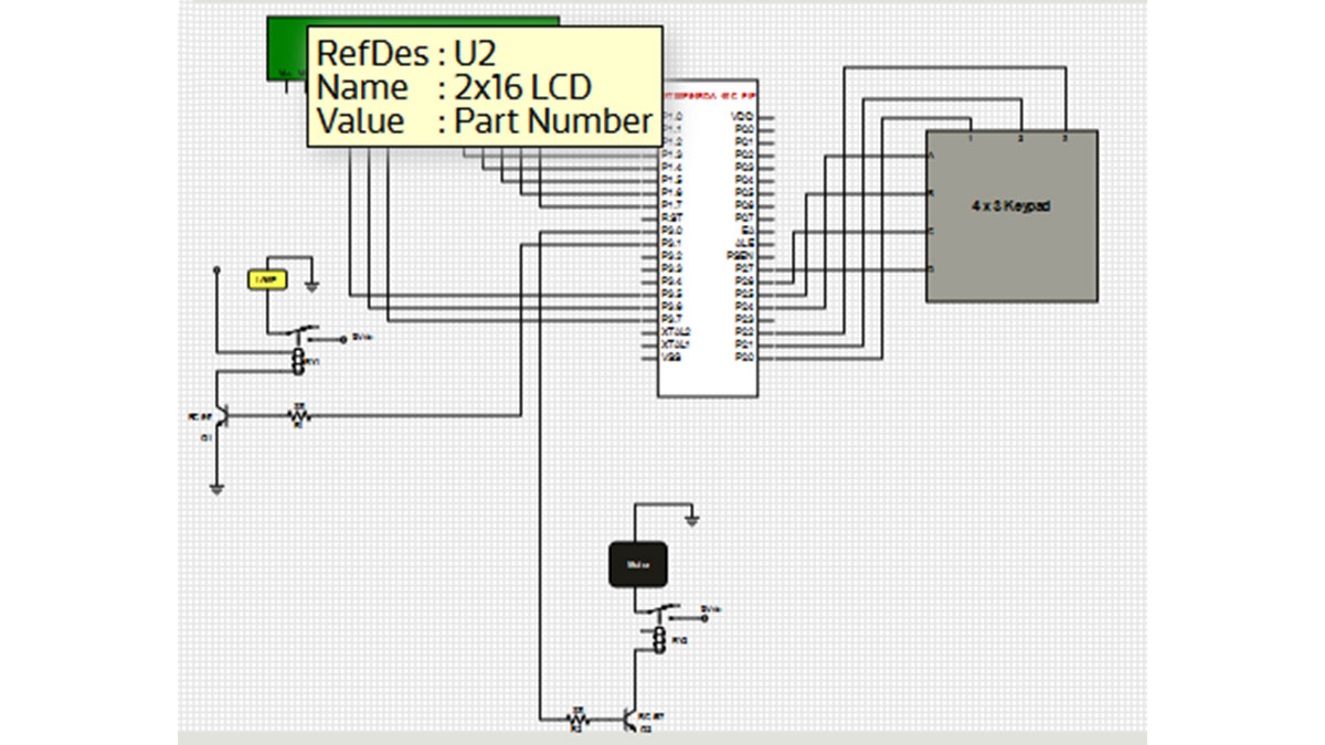
The circuit consists of 8051 series controller, 4×3 keypad, LCD, relays and two loads. LCD data pins are connected to port1 and control pins RS, RW, EN pins are connected to P3.7, P3.6 and P3.5 respectively. The keypad is connected to port 2 of the controller while the LCD is used to display the information. In addition, the lamp and motor are connected to P3.0 and P3.1 through the relays. These are used to indicate circuit breaker state. Moreover, BC547 transistors are used to drive the relays where 5V relays are used to drive the AC loads. While giving the connections, there should be no common connection between AC and DC supplies. Furthermore, a 5V power supply is used to provide regulated 5V DC to the controller.
This project distinctly provides security and convenience to electrical maintenance personnel. This may help avoid fatal accidents to line man, which can be used in establishments such as building offices, hotels, industries and houses. It is a simple project with commonly available components that helps save life.
Source : Password Based Circuit Breaker
-
What is the primary purpose of this project?
To prevent fatal electrical accidents during line repairs by requiring a password to control the circuit breaker. -
Which microcontroller is used in the system?
The system uses the SST89E54RDA-40-C-PIE, an 8-bit microcontroller from the Flash Flex family. -
How are the LCD control pins connected?
The RS, RW, and EN pins are connected to P3.7, P3.6, and P3.5 respectively, while data pins connect to port1. -
What components drive the AC loads in this circuit?
BC547 transistors are used to drive 5V relays which then switch the AC loads. -
How does the system indicate the circuit breaker state?
A lamp and a motor are connected through relays to indicate the state of the circuit breaker. -
Where is the keypad connected within the controller?
The keypad is connected to port 2 of the controller. -
What type of power supply is required for the controller?
A regulated 5V DC power supply is used to provide power to the controller. -
Why must there be no common connection between AC and DC supplies?
This safety measure is necessary when making connections to ensure proper isolation between AC and DC circuits.
