If you want an article on general 74hc595 shift register usage with detailed explanition on how it works/what it’s doing, you want this article here: http://bildr.org/2011/02/74hc595/ The following code and library are compatible with arduino software 1.0+ ONLY. You can download the newest version of the arduino software here.
Earlier this year we did an article on using the 74hc595 shift register with your arduino. It has been, by far, our most popular article. It seems that a lot of people want to control a lot more LEDs (or other) than the arduino can do without help. So we actually went to the guys over at sparkfun and said… “Hey! Let’s make this even easier”. And so we came up with the 74hc595 breakout board.
So now you find your self asking “Why?” Well… chainability! Using right-angle headers you can chain a ton of these together. AND! With the code we have for you, you get an additional 8 digital outputs per board you have connected. That means if you have 1000 of these chained together, you will be able to say “setPin 7,432 HIGH”, and BAM! Just like that pin 7,432 goes HIGH. It will literally be like you have more digital outputs on your arduino, no funny business.
Hooking it up
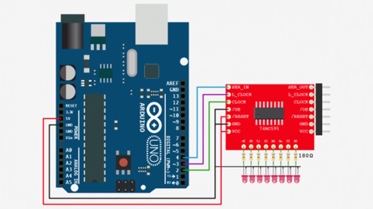
At first this board may look confusing to hookup… But just click on the illustration to get a better view of how it is hooked up. We won’t be using Reset, so just connect that to power, and connect /OE to ground (enables the board). For VCC you can connect this to 3.3 or 5V on your arduino, and the outputs will just reflect this. So if you power the board with 3.3v, the outputs on the board will output 3.3v as well. We just need 3 digital pins to control the board, and after that we are done.
You can chain as many of these as you would like. I used right-angle header pins to make it modular and clean. I picked up some 7 pin right-angle headers from digikey to make it even easier. But you dont have to use header pins for this if you don’t want. You can easily just wire them together too. Either way, see the illustration below to see how you do this.
For more detail: Arduino: Individually Control Shift Register Pins
