Introduction
This tutorial is brought to you by BreakoutBros.com. Access the complete version by following this link.
Having explored the Particle Photon, I felt inclined to revisit one of our tutorials and introduce IoT (Internet of Things) capabilities using the Photon. In this guide, I will demonstrate how to enable the Particle Photon to send you emails by integrating this functionality into our RFID Badge Scanner with LCD tutorial.
If you haven’t yet explored the RFID Badge Scanner with LCD tutorial, your initial step is to visit the article and set up the necessary components. This setup enables you to scan an RFID badge and showcase a personalized “welcome home” message linked to the user associated with the RFID tag.
What you will need
Apart from the components required for the RFID badge scanner, you’ll also require the following materials:
– Particle Photon
– 3x 10K resistors*
– 3x 2k resistors*
– 3x NPN 2222A Transistors*
– Wires and Breadboard*
(*Note: These items are available on Amazon or at electronics stores. Alternatively, you can explore Arduino Starter Kits, which typically include these fundamental components.)
5V to 3.3V level shifting
In this tutorial, we’ll utilize the Arduino to establish direct communication with the Particle Photon by employing three distinct I/O pins. When the first pin registers as High, it signifies the scanning of the 1st user’s badge. Similarly, High readings from the second and third pins indicate the scanning of the 2nd and 3rd user’s badges, respectively.
Notably, the Particle Photon operates on 3.3V logic, while the standard Arduino functions on 5V logic. To ensure secure communication through I/O pins, it’s essential to create a level shifter that transitions 5V to 3.3V. While a direct connection of 5V to the Particle Photon I/O may function, it’s not advisable due to the potential strain and probable damage to the pins. This caution is especially crucial when dealing with Analog pins, as it exerts excessive pressure on the analog-to-digital converter. Particle explicitly advises against directly linking 5V to these pins.
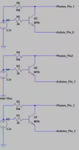
The 5V to 3.3V level shifter circuit involves a straightforward setup consisting of an NPN transistor and specific biasing resistors.

This setup involves converting a 5V output from the Arduino Pin to a 3.3V input on the Photon pin. When the Arduino Output is at 0, the corresponding Photon input pin will also register as 0.
You’ll require three of these circuits, each designated for the pins interfacing between the Arduino and Photon. Please adhere to the provided pinout instructions below for proper connectivity.
Subsequently, connect these three circuits using a breadboard. The Particle Photon starter kit includes one, and it is also included in the Arduino Starter Kits.
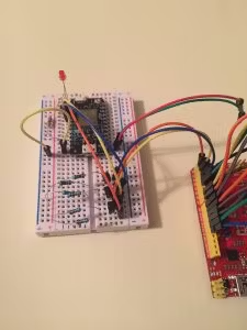
Power up the Photon through the Arduino’s 5V output by linking VIN on the Photon to the Arduino’s 5V supply. This pathway will pass through the Photon’s voltage regulator, adjusting the voltage to the required 3.3V. Remember to establish a connection between GND on the Photon and GND on the Arduino.
With both your Arduino and Particle Photon configured for communication using a 5V to 3.3V level shifter, it’s time to initiate the coding process for the Particle Photon.
As mentioned in the Particle Photon Review, an online Integrated Development Environment (IDE) is utilized for programming purposes. Navigate to www.Particle.io/build and log in to your Particle account. Create a new program tailored to publish an event based on specific inputs read by the Photon from the Arduino. This event will serve as a trigger for sending you an email later on. Additionally, the code will incorporate functionality for the LED to visually indicate when and to whom an email is being sent, with the LED blinking at varying rates based on the recipient.
Particle Photon Code
First define all the global variables
int led1 = D0; //LED to show changes in states
int led2 = D7; //LED to show changes in states

int firstBitPin = 1; //Pin that will be reading the first Bit to know state
int secondBitPin = 2;//Pin that will be reading the second Bit to know state
int thirdBitPin = 3; //Pin that will be reading the third Bit to know state

int firstbitState = LOW; //variable to store the state of the first Bit
int secondbitState = LOW;//variable to store the state of the second Bit
int thirdbitState = LOW; //variable to store the state of the third Bit


int LEDDelay = 1000; //Variable used to change the LED blink timer based on what Bits are high
This comprises the complete list of pins to be utilized and the data bits to be stored according to the Arduino outputs. It also specifies setting the LED blink rate to one second.
Following this, we’ll delve into the setup loop, primarily focusing on defining pin outputs and initializing variables.
void setup() {


  pinMode(led1, OUTPUT);  //Set the LED pin to an Output
  pinMode(led2, OUTPUT); //Set the LED pin to an Output

  pinMode(firstBitPin,  INPUT);//Set the BIT 1 pin to an input(used for transfering who is scanned)
  pinMode(secondBitPin, INPUT);//Set the BIT 2 pin to an input(used for transfering who is scanned)
  pinMode(thirdBitPin,  INPUT);//Set the BIT 3 pin to an input(used for transfering who is scanned)

  digitalWrite(firstBitPin,  HIGH); //enable pullup
  digitalWrite(secondBitPin, HIGH); //enable pullup
  digitalWrite(thirdBitPin, HIGH);  //enable pullup

  digitalWrite(led1, LOW); //Make sure LED 1 starts in LOW state

}
The final section of the code serves as the main loop. It directs the photon to respond according to the data it receives from the Arduino’s Bits.
void loop() {
  firstbitState = digitalRead(firstBitPin);  //Read bit 1 and store
  secondbitState = digitalRead(secondBitPin);//Read bit 2 and store
  thirdbitState = digitalRead(thirdBitPin);  //Read bit 3 and store

  if(firstbitState == HIGH) // This will only work for 3 of the combos;(0,0,1)(0,1,0)or (1,0,0)
  {
      Particle.publish("RFID_HOME","JOSH"); // Particle Command to publish the Event "RFID_HOME" with the data JOSH
      LEDDelay = 250;                       // this means Josh's badge was scanned. we also change the LED blinking to 250
      delay(5000);                          // 5 second delay after publshing, this will prevent 2 publishes from one eveent from the arduino.
  }
  else if(secondbitState == HIGH)
  {
      Particle.publish("RFID_HOME","BRAD");  // Particle Command to publish the Event "RFID_HOME" with the data BRAD
      LEDDelay = 500;                        // this means Brads's badge was scanned. we also change the LED blinking to 500
      delay(5000);                           // 5 second delay after publshing, this will prevent 2 publishes from one eveent from the arduino.
  }
  else if(thirdbitState == HIGH)
  {
      Particle.publish("RFID_HOME","SAM");   // Particle Command to publish the Event "RFID_HOME" with the data SAM
      LEDDelay = 1000;                       // this means Josh's badge was scanned. we also change the LED blinking to 1000
      delay(5000);                           // 5 second delay after publishing, this will prevent 2 publishes from one event from the arduino.
  }
  else
  {
      LEDDelay = 2000;                      //If none of the bits are set, we store 2 seconds for the blinking, this is"normal" blink time

  }
    digitalWrite(led1, HIGH);               //Set LEDs high as a heartbeat
    digitalWrite(led2, HIGH);
    delay(LEDDelay);                        //Use the delay stored above
    digitalWrite(led1, LOW);
    digitalWrite(led2, LOW);                //Set LEDs LOW as a heartbeat
    delay(LEDDelay);                        //Use the delay stored above
}
The primary loop initially retrieves and stores the pin states into their respective variables. Subsequently, it determines the active bit and triggers the execution of the Particle.publish(“EVENT”, “DATA”) command. The initial input in the Particle.publish command represents the “event,” while the second input denotes the “DATA.” Here, we label this event as “RFID_HOME,” with the user badge name serving as the data input. Additionally, a distinct LED blink duration is assigned for each user, allowing for visual identification when the Photon detects a specific badge.
To prevent multiple event transmissions from a single Arduino scan, a delay follows the execution of the Particle.publish command. The remaining segment within the code loop manages LED blinking at the LEDDelay frequency. For access to the Photon Particle code associated with this tutorial, it’s available here.
Setting up IFTTT For the IoT Email
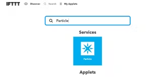
With the Particle device publishing the RFID_HOME event to the Particle Cloud, your next step involves configuring a service to monitor the publication of this data. In this tutorial, If This Then That (IFTTT) will be employed. Begin by visiting ifttt.com and setting up an account.
Search for “Particle” and select the Particle Icon within the services section:
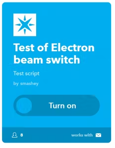
Afterward, proceed to choose an Applet that utilizes Email. Scroll through the options and select “Test of Electron Beam Switch” below.
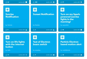
Flip the switch to turn this applet on
Once the Applet is on it will allow you to edit.
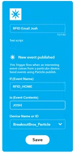
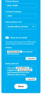
There’s a need to save and revisit the Applet for configuring the Email section, for reasons unknown. Here’s the email format: The subject line will read as “{EventContents} has entered the front door,” while the body text will be: “Hey, your {DeviceName} has logged that {EventContents} has entered the front door. Welcome them Home.”
To complete the IoT setup, two additional applets need to be set up for the other badge names – SAM and BRAD.
![]()
Testing the Particle Photon Email
After completing the setup, it’s essential to verify the Particle Photon’s functionality. Test it by individually setting each pin (1 through 3) to a high state on the Particle Photon for a few seconds. Confirm the LED starts blinking at varying rates for each pin activation. Additionally, check the email associated with ifttt.com to ensure the reception of the emails.
Specifically, setting Pin 1 to HIGH triggers the “JOSH” email, Pin 2 activates the “BRAD” email, and Pin 3 initiates the “SAM” email. It’s crucial to keep the other pins at a low state during this process; otherwise, the email associated with the first name in the IF statements will be sent erroneously.
Upon successful testing of this functionality, proceed to connect the RFID Badge Scanner with the LCD system.
Arduino Code sent to Particle Photon
Given that the RFID Badge Scanner is retrieving the RFID badge and associating a Name with each badge ID, your task is to configure the pins to go HIGH and LOW for each Name. Then, integrate code that ensures these pins are set accordingly whenever the Badge ID is detected.
Commence by defining the new pins and arrays for Pin Data.
///Email Variable
int outFirstBitPin = 0; //Pin that will be connected to Photon for bit one data
int outSecondBitPin = 1;//Pin that will be connected to Photon for bit two data
int outThirdBitPin = 2; //Pin that will be connected to Photon for bit three data

int RFID_JOSH[]   = {1,0,0}; //Parallel Data for JOSH tag to send to Photon
int RFID_BRAD[]   = {0,1,0}; //Parallel Data for BRAD tag to send to Photon
int RFID_SAM[]    = {0,0,1}; //Parallel Data for SAM  tag to send to  Photon
Next add in code that will set these pins based on the name read:
 if(Tag_Name != "i")
            {
                  lcdprintwelcome(Tag_Name);

                  if(Tag_Name == "Brad") //If the name is BRAD we send the parallel data to the Photon to send the email that Brad Scanned
                  {
                    digitalWrite(outFirstBitPin,  RFID_BRAD[0]);   //Send first bit data for Brad
                    digitalWrite(outSecondBitPin, RFID_BRAD[1]);   //Send second bit data for Brad
                    digitalWrite(outThirdBitPin,  RFID_BRAD[2]);   //Send third bit data for Brad

                    delay(5000); //Wait 5 seconds after sending the data to ensure the Photon reads it during its loop

                    digitalWrite(outFirstBitPin,  0);   //set data back to 0
                    digitalWrite(outSecondBitPin, 0);   //set data back to 0
                    digitalWrite(outThirdBitPin,  0);   //set data back to 0
                  }
                  else if(Tag_Name == "Josh") //If the name is BRAD we send the parallel data to the Photon to send the email that JOSH Scanned
                  {
                    digitalWrite(outFirstBitPin,  RFID_JOSH[0]);   //Send first bit data for Josh
                    digitalWrite(outSecondBitPin, RFID_JOSH[1]);   //Send second bit data for Josh
                    digitalWrite(outThirdBitPin,  RFID_JOSH[2]);   //Send third bit data for Josh

                    delay(5000); //Wait 5 seconds after sending the data to ensure the Photon reads it during its loop

                    digitalWrite(outFirstBitPin,  0);   //set data back to 0
                    digitalWrite(outSecondBitPin, 0);   //set data back to 0
                    digitalWrite(outThirdBitPin,  0);   //set data back to 0
                  }
                  else if(Tag_Name == "SAM") //If the name is BRAD we send the parallel data to the Photon to send the email that SAM Scanned
                  {
                    digitalWrite(outFirstBitPin,  RFID_SAM[0]);   //Send first bit data for Sam
                    digitalWrite(outSecondBitPin, RFID_SAM[1]);   //Send second bit data for Sam
                    digitalWrite(outThirdBitPin,  RFID_SAM[2]);   //Send third bit data for Sam

                    delay(5000); //Wait 5 seconds after sending the data to ensure the Photon reads it during its loop

                    digitalWrite(outFirstBitPin,  0);   //set data back to 0
                    digitalWrite(outSecondBitPin, 0);   //set data back to 0
                    digitalWrite(outThirdBitPin,  0);   //set data back to 0
                  }
                  lcdprintmain(); //Go back to Main scan screen
            }
            else
            {
                lcdaccessdenied();//If the read tag isnt in our data base, we will print an Access Denied message
                delay(2000);
                lcdprintmain(); // refresh to home screen
            }
Once the criteria for identifying a valid tag’s success is met, upon finding a name matching “Josh,” “Brad,” or “Sam,” the corresponding pin output is transmitted to the Particle Photon. To allow the Photon time to register the pin change, a 5-second delay is introduced. Following this delay, the pins revert to 0 to prevent further email transmission. Find the complete Arduino code here.
With the successful integration of the Particle Photon, the RFID Badge Scanner with an LCD becomes an IoT-enabled device. Whenever a specified badge is scanned, an email notification is sent. By incorporating this system into your front door and controlling a lock solenoid, you create a monitoring setup for your house’s front door lock. This setup alerts you via email whenever someone uses a badge, providing awareness of home activity regardless of your physical presence.
I trust you found value in and gained insights from this tutorial. To stay updated on future articles, kindly subscribe. We’re planning to introduce additional functionalities to the RFID Badge Scanner, so stay tuned for more updates!