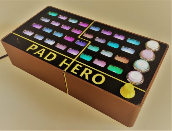
A group of three students present you PAD HERO, our Arduino based Guitar Hero game. This project was submitted to ‘Creative Electronics’, a Beng Electronics Engineering module at University of Málaga, School of Telecommunications (https://www.uma.es/etsi-de-telecomunicacion/).
The aim of this Project was to replicate the popular game Guitar hero on Arduino. We wanted to keep it as simple as possible so we gave it the retro/arcade touch it has. The setup uses a SAV MAKER I as a controller, an alternative to Arduino Leonardo, assembled by us.
We hope you enjoy this instructable as we did enjoy making it! Also, if you need help with some of the steps or want to collaborate do not be afraid of asking in the commentary section!
Step 1: Suplies
Things inside the PAD HERO:
- Addressable led strip (WS2812B or similar 5V addressable) (WS2812B)
- 1 SAV-MAKER-I (alternative to Arduino Leonardo). If anyone wants to make and use this board instead of using Arduino Leonardo or another board alike, there is the link of github where you will find all the required information to do so.
- Big arcade buttons (buttons)
- Toggle switch (3 pin switch)
- Individual addressable led for buttons (individual WS2812B)
- Power supply at least 3 amps (power supply)
- Wire suitable for welding
- More than 500gr of PLA
- Potentiometer (less than 1k Ohm)
- Small speaker or buzzer
- Assortment of screws (metric 3)
Tools that I used for this build:
- Soldering kit
- Tin and flux
- Instant glue for rigid plastic
- 3D printer
- Hot melt glue to fix microcontroller
Step 2: Designing/3D Printing
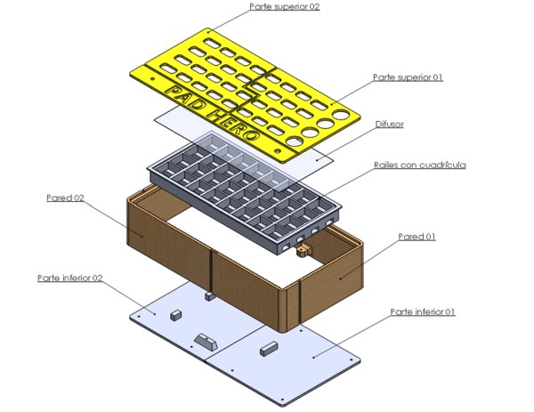
All the design has been done in Solidworks with the collaboration of the industrial designer who works at A3dei
You can download the stls on thingiverse or at the same time as the code on github.
Most of the pieces (at least the exterior) are configured to be printed on a small surface, for example in an Ender 3, the design of the union between pieces is integrated into the general aesthetics of PAD HERO, some trims have been added to cover the joints.
Things to keep in mind:
- “Parte superior 01.stl” and “Parte superior 02.stl” are designed to effect a filament change during printing
- “Railes con cuadricula.stl” is long piece, you will need a large printing surface or section the STL, later glue them together.
- “Difusor” is not an STL, it is a translucent plastic sheet reused from a notebook, cut with scissors until it fits, at least 0.3mm thick.
The sides and the floor do not have any complications in their assembly, however you should pay attention to aligning the LEDs (“Parte superior 01.st”, “Parte superior 02.stl” and “Railes con cuadricula.stl”, it is advisable to draw the final position with a marker before applying the glue
The next version of the design could have a hole to fix the speaker to the outside, since inside the box the sound power is limited. But with the current build you can use any speaker.
Step 3: Soldering
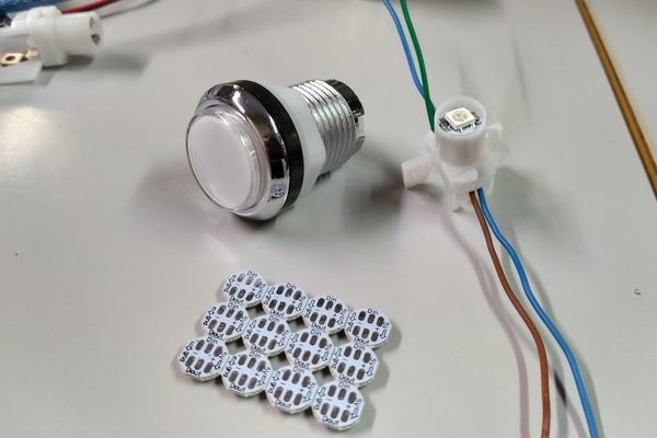
Replacing the button’s LEDS with our own. First you need to solder the neopixel single LEDS into some cables. Then disassembling the buttons and replacing the led with the neopixel we attached the cables.
Led Stripe. Either if you have a long one(you will need to cut it) or 4 short ones you need to solder them as the schematic below shows, just solder small wires in the led stripes in order to test first. To test it we used some electrical quick connectors as you can see in one of the photos posted. Then the button will be one more accessible LED in the matrix.
For the potentiometer and the switch button there is not much more to say.
Step 4: Schematic and Wiring
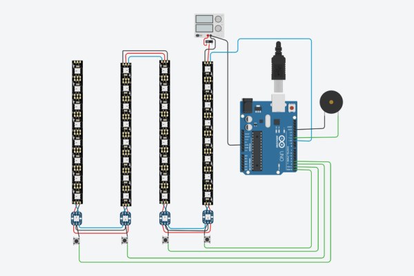
Insert the led stripe into the 3d printed matrix case. Once we got the buttons ready to go, we shall proceed to connect them with the led stripe and fit them inside the case. Then put the light diffuser sheet in between the matrix and the top part of the case. Make sure the leds are in line with the holes and glue it. If you succeed in this task you can start wiring the buttons and the led stripe all toguether, make sure you respect the Data in/Data out pins on the new buttons. We had some problems with that.
You can choose between connecting the switch to the 5V source or directly to the AC cables coming from outside. It´s better to keep the power supply disconnected from the AC, but take special care when wiring it.
If you want to improve our design, you could include a debounce RC circuit in the buttons. We really had a struggle with that that could not be solved via software.
Now it’s time to start joining the wires with the SAV-MAKER-I as the schematic shows and we will be ready to test it.
Step 5: Arduino Program
For this Project we used one of the most popular libraries for LED controlling, the Adafruit NeoPixel Library in order to control our led strip. We also used the pitches.h library combined with the tone() function to control the buzzer tones.
We structured the code as a state machine where you can find the intro animation, the selection of the song you want to play with, the main game and a finale animation with the score you got.
With the object to control both leds and button interruptions we tried to keep it as raw as possible using a flag and the millis() function as a fake timer interrupt inside the main loop.
The code itself is probably not the most efficient code ever, but it works pretty flawless. In order to make this project more accessible (since it needs at least 4 interrupt pins) we want to recommend the library EnableInterrupt by GreyGnome (EnableInterrupt) in case your arduino board does not have that many digital pins usable for interrupts.
You can find all the code used here [CODE]. (V2) (NEW GAME MODEs: PIANO AND SIMON SAYS)
The code is still in the development phase, we are aware that the gameplay can be improved, more animations can be added and the sound can be improved. All the necessary modifications will be made to achieve a solid game.
Disclaimer: The whole program is programmed from scratch but we got ideas for some parts of our code from another instructable by oKgeeg.
Step 6: Lets Play!
Plug in the PAD HERO and you will se an animation where random leds turn on while a song is played.
If you press any button the game will transfer you into a select song menu. You can select the song you want to play with by pressing the left button or the right button. To confirm the song just press one of the central buttons.
Once you confirmed the song the game will start. Then you will see some leds falling from the top, the goal of the game is pressing the right button at the right time to keep playing. You fail if you dont press the button in time or press the wrong button. In that case the game will display your score and wait for you to press any buton to start again from the animation.
We adjusted the difficulty so the leds travel faster as you dont fail. Even us cannot get the maximum score!
Source: PAD HERO (Guitar Hero Using Arduino)