Summary of Thermal Camera
This article details a DIY project to build a low-cost thermal infrared camera using an Arduino, addressing the high expense of commercial FLIR cameras. The device employs a single MLX90614 sensor scanned by servos to capture images of stationary objects. While affordable, the raster scanning method results in slow image acquisition, making it unsuitable for moving subjects. Assembly requires soldering skills and typically takes a weekend.
Parts used in the DIY Thermal Camera:
- Arduino Project Enclosure
- 2x Small Servo
- Pan/Tilt Bracket
- Arduino Uno or variant
- Logic Level Converter
- Straight Break Away Headers
- Right Angle Break Away Male Headers
- Microsoft LifeCam VX-700
- Protoshield PCB for Arduino
- MLX90614ESF-DCI Sensor
- Ribbon cable (approx. 1 foot)
- .100 KK Housings & Terminals 6 Cir.
- PCB board for laser and sensor
- Laser switch
- Aiming laser
- Small nuts and bolts (#2-56 x 1/4")
- Soldering iron
- Solder
- Wire cutters
- Drill or Dremel drill
Have you ever had the desire to see what can not be seen? I never had the ability to see in thermal infrared, and it is rather cool to be able to see in the thermal infrared part of the electromagnetic spectrum. Unfortunately, most thermal (FLIR) cameras are very expensive. In 2011 cameras frequently cost several thousand dollars. This project was created to develop a cheaper solution at a fraction of the cost.
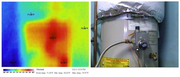
The primary reason for the cost difference is the thermal infrared sensor. Instead of having a 2 dimensional array of sensors, a single sensor is moved in a raster scan pattern. Moving this single sensor takes time. So while you have fewer costly sensors, it takes longer to take a picture. This means the camera can not take images of moving objects, and the objects have to be very still during the scanning.
The original instructions can be found on my web sitehttp://www.centralnexus.com/thermal/. These instructions require some soldering ability. It can take most of your weekend to assemble this camera once you have the parts. If you’re good with soldering you may be able to assemble it faster.
Step 1: Get The Parts
The following are the parts used in creating this camera. The links to the web sites that carry these parts can be found on my web site. It’s been a while since these parts were ordered, and you may need to find other web sites with similar parts if a part is no longer available. It’s highly recommended that you do not substitute the MLX90614ESF-DCI sensor because it’s the most accurate with the narrowest field of view.
Arduino Project Enclosure
2x Servo – Small
Pan/Tilt Bracket
Arduino Uno or an Arduino variant
Logic Level Converter needed when using a 5 volt version of the Arduino, which is the most common version.
Break Away Headers – Straight
Break Away Male Headers – Right Angle
Microsoft LifeCam VX-700
Protoshield PCB for Arduino. Almost any Arduino prototype shield will do.
MLX90614ESF-DCI. This model has the best accuracy and narrowest field of view.
About a foot of ribbon cable. Almost any wire will do. At least 5 wires are needed to connect the sensor to the Arduino and laser.
.100 KK Housings & Terminals 6 Cir. (2.54mm) for the ribbon cable.
PCB board for holding the laser and sensor.
A switch to turn the laser on or off.
A laser for aiming the sensor and aligning the pictures.
Small nuts and bolts (#2-56 x 1/4″) to attach the servos.
The following additional parts and tools are used in creating this camera.
Soldering iron
Solder
Wire cutters
A standard drill or a Dremel drill for creating holes in the case
Step 2: Wire The Parts
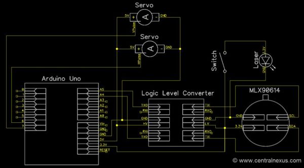
Wire the Arduino with its parts like in this diagram. Some soldering will be required.
Step 3: Assemble The Parts
After wiring all the parts together, it’s time to assemble the parts. I made holes in the case for the visual spectrum camera and the servo motor. The Arduino was put on the bottom of the case. I plugged in the shield into the Arduino. I plugged in the sensor and laser into the shield, and I attached the sensor with laser to the top of the servo brackets.
For more detail: Thermal Camera
- Why is this project cheaper than commercial thermal cameras?
The cost difference arises because this design uses a single sensor moved in a raster scan pattern instead of an expensive two-dimensional array of sensors. - Can this camera take pictures of moving objects?
No, the camera cannot take images of moving objects because the single sensor must move slowly to scan the scene. - What specific sensor model is recommended for best accuracy?
The MLX90614ESF-DCI sensor is highly recommended because it offers the best accuracy and narrowest field of view. - How long does it take to assemble this camera?
Assembly typically takes most of a weekend, though those skilled at soldering may complete it faster. - Is a logic level converter required for this build?
Yes, a logic level converter is needed when using the common 5 volt version of the Arduino. - What tools are necessary for creating holes in the case?
You need a standard drill or a Dremel drill to create holes in the case for the visual spectrum camera and servo motor. - What is the primary function of the laser in this project?
The laser is used for aiming the sensor and aligning the pictures during the scanning process. - Do I need to substitute parts if they are unavailable?
It is not recommended to substitute the MLX90614ESF-DCI sensor, but other parts may be sourced from different websites if original links are outdated.