Summary of Opensource Ornithopter Prototype. Arduino Powered and Remote Controlled.
This article details the design and construction of an Arduino-powered, remote-controlled ornithopter prototype. The project covers wing span and flapping frequency design, selection of electric motor, ESC, battery, and electronic components like Arduino boards and servos. Construction aspects include CNC cutting of fiberglass parts, 3D printing nylon gears, assembly of a dual-stage gearbox with metal and nylon gears, wing and tail creation using carbon fiber rods and nylon fabric, and final assembly with various hardware. The author emphasizes a transverse shaft flapping mechanism for wing symmetry and provides complete parts lists for each stage.
Parts used in the Opensource Ornithopter Prototype:
- 2627 4200KV brushless outrunner motor
- Turnigy 2627 Brushless 300-Size Heli Motor 4200kv (alternative motor)
- nVision LiPo 2S 7.4V 900mAh 30C battery
- SWIFT 20A Speed Controller (ESC) with BEC
- Arduino Nano (Iskra Nano Pro as budget option)
- Arduino Uno (for remote control)
- 2x Mbee 868 version 2.0 wireless modules
- 2x HITECH HS-65MG micro servos (or equivalents)
- Li-Pol Power Bank 5V 2000 mA (for remote control)
- Slider potentiometer module (Troyka)
- 3D Joystick module (Troyka)
- Fiberglass sheet material (2 mm thickness, ~1x1m)
- Carbon fiber rods (4mm, 3mm, 1.5mm diameters)
- Blue nylon fabric ("Ripstop") 1.5x5m
- Double sided polypropylene adhesive tape (19mm width)
- 3D printed nylon parts: base (2 pcs), gear 72 teeth, gear 84 teeth left & right (2 pcs each), tail_joint, wing_joint (2 pcs)
- Metal gears: 8 teeth, 2.3mm bore; three 9 teeth, 2mm bore pinion gears
- Bearings: flanged F684ZZ 4x9x4 mm (4 pcs), FMR52ZZ 2x5x2.3 mm (3 pcs)
- 2mm diameter, 45mm stainless steel shaft
- Adjustable steering servo links (HSP 02157 or similar, 4 pcs)
- Micro drill chucks 0.5-3mm (2 pcs)
- Screws: M2 (various lengths), M2.5, M3 (various lengths), M4 (various lengths), nylon M3 screws
- Nuts: Hex M2, M2.5, M3, M4, nylon M3
- Washers: M2
- Standoffs/spacers: Nylon M3x10mm or M3x20mm
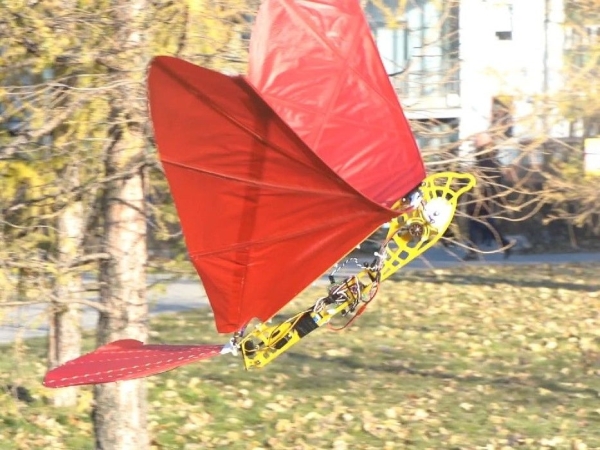
This instruction is a story about how I made an ornithopter prototype.
For those who do not know, an ornithopter is a machine designed to achieve flight by flapping wings like a real bird. The idea was to create an ornithopter from scratch, to control it remotely, and of course to make it fly.
Please do not judge; I’m not the professional of the aircraft industry. So, not everything works as I would like, but it still does.
Instead of photos, this instruction prevails by graphic schemes. The real result can be seen in a multi-series video on the Youtube channel. If you enjoy this guide, subscribe to the channel.
The instruction will be corrected and supplemented with material over time. The ornithopter will also be improved.
At this moment the instructable can be divided into the following chapters:
- Video review.
- Design. Wingspan, Weight and Flapping Frequency
- Design. Flapping Mechanism Overview.
- Preparation. Motor, ESC, and Battery.
- Preparation. Eletronic components.
- Preparation. CNC Cutting.
- Preparation. 3D Printing.
- Preapration. Screws, Bearings, Metalware and other stuff.
- Design. Gearbox.
- Assembling. Gearbox.
- Wings and Tail. Design and Components.
- Wings and Tail. Patches.
- Making. Wings.
- Assembling. Wings.
- Making. Tail.
- Assembling. Tail.
- Programming. XOD. UART byte protocol.
- Programming. ESC.
- Assembling. Wiring diagram.
- Assembling. Final steps.
- Programming.
Step 1: Video Review.
Step 2: Design. Wingspan, Weight and Flapping Frequency.
So, how often do birds flap their wings?
The flapping rate of bird wings is determined by wing area. For example, for a stork It is enough to flap wings with a frequency of 2 strokes per second, a sparrow has to make 13 strokes per second, and a hummingbird – up to 80 strokes per second. I wanted to make a large ornithopter. Therefore the wing area should be large too. To calculate the area of the wing you should know the wingspan. So, wingspan became the first parameter to chose. I decided to make an ornithopter with a wingspan in the range of 1200-1400 mm.
I searched the Internet for existing ornithopter designs and analyzed the dimensions. Seems that most ornithopters are made in a specific size row. Hobbie ornithopters can be sorted by wingspan (from 660 mm to 3000 mm) and by flight weight. My ornithopter with a 1200-1400 mm wingspan will be somewhere in the middle of this scale, not large, but not small either.
I was looking for design information on hobby forums, in the ornithopter specifications, and in a variety of Youtube videos. I figured out that ornithopters with such wingspan should perform from 5 to 7 flaps per second and have a flight weight in the range from 300 to 500 g. I chose the average flight weight value – 400 g. Since I have no experience in building airplanes and flapping birds, I chose all values empirically and mostly hoping for luck.
With the approximate flapping rate (5 to 7 Hz), I can get to design the flapping mechanism.
By now, summing up ornithopter parameters:
- Wingspan ≈ 1200 – 1400 mm;
- Flapping rate ≈ 5 – 7 Hz;
- Flight weight ≈ 400 g.
Step 3: Design. Flapping Mechanism Overview.
Flapping mechanism is the most critical part of the ornithopter. It converts the electric power from the battery to the flapping motion of the wings. This system is the most complex to design and fabricate because it must withstand vast forces which reverse direction several times a second while at the same time being extremely light and durable.
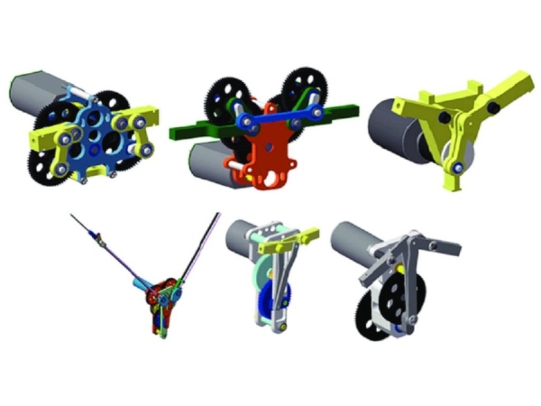
There are many kinds of flapping mechanisms (Pic. 1). Here are the most used ones.
Staggered Crank
The staggered crank design (Pic. 2) is the most basic of the flapping mechanism design. The connector rods are staggered in a measured distance and angle to ensure that the left and right wing are flapping symmetrically. This design is favored by a hobbyist who wants to attempt to make their own ornithopter using household items. Most often these mechanisms are driven by a rubber band.
Single Gear Crank
The single gear crank design (Pic. 3, 4) looks simple however it is more complicated than it seems. The center point where the connector rod and the wing hinges are connected to each other has to expand and contract as the mechanism flaps. Contracting and expanding at a very high frequency could result in component failure.
Dual Gear Crank
This design features two gears that control each wing hinges separately. There is a different variation to the drivetrain design. The pinion wheel can drive both secondary gears (Pic. 5, 6, 7). So, the secondary gears will rotate in the same direction with each other. In the different design, the pinion gear rotates the secondary gear, and this secondary gear rotates another secondary gear (Pic. 8). The secondary gears would turn counterclockwise to each other. This design is much simpler to implement and reduce the wing symmetry misalignment.
Transverse Shaft
The transverse shaft design (Pic. 9, 10) is the other variation of dual gear crank mechanism. This design allows for the most symmetrical flap. However, it is the heaviest and the most complicated design. The rotating gears and the flapping wings are not on the same plane thus the connector rod has to be able to rotate. The connector rod has a ball bearing inside, and this adds weight to just the component itself. The number of gears used in this design is more than any other design. The transverse shaft design is usually used for large ornithopters where weight could be overcome by large wings.
I decided to choose a design with a transverse shaft. The size of my ornithopter allows the use of an additional mass of the mechanism. Besides, it is easy to make such design by cutting the sheet material as the planes of the gears are parallel to the plane of the body.
Step 4: Preparation. Motor, ESC, and Battery.
Motor selection.
The motor should be small in size. Big size motors weight a lot and weight can be very critical for the design. At the same time, the electric motor should be sturdy to provide enough torque to overcome air resistance.
To increase the torque and reach the necessary flapping frequency, I’m going to use a gearbox. In this case, I can take a weaker motor with a higher revolution per minute (rpm) value.
Taking into account the ornithopter dimensions the 300 – 400 sized electric hobby motor should fit perfectly. Hobby motors of this size can be brushed or brushless. Basically, you can find them in medium-sized RC boats and helicopters.
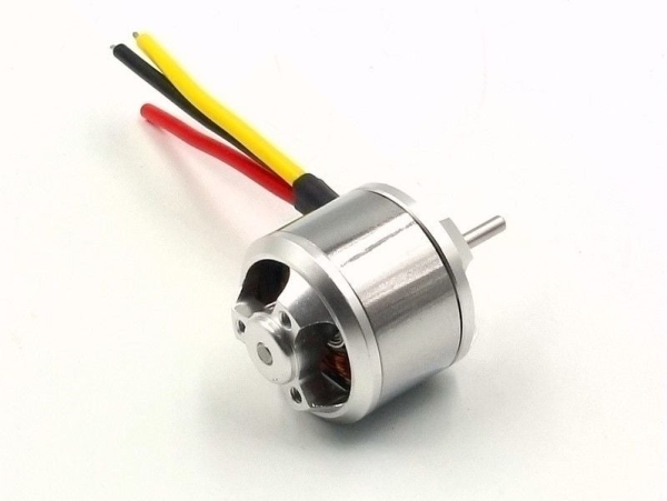
I purchased this one (Pic. 1):
1 x 2627 4200KV brushless outrunner motor ≈12$;
A possible replacement (Pic. 2):
1 x Turnigy 2627 Brushless 300-Size Heli Motor 4200kv ≈ 15$;
Pay attention to the important detail. You need an outrunner motor. Mounting holes of the motor must be on the same side as the output shaft. So, housing which is close to the output shaft has to be immovable.
Main motor characteristics:
- Output shaft diameter: 2.3 mm;
- Max current: 22A / 20S;
- Voltage: 2 – 3S;
- Dimension: 26mm x 27mm, 41mm;
- Weight: ≈ 39g;
Brief label explanation:
First, 4 digits at the description (2627) are the motor dimensions. The first pair shows a diameter of the motor (26mm) while the second pair shows the length (27mm).
A “Kv” value refers to the constant velocity of a motor. It is measured by the number of revolutions per minute (rpm) that a motor turns when 1V (one volt) is applied with no load attached to that motor.
For example:
This 2627 4200Kv brushless motor can be powered by 2S (7.4V) or 3S (11.1V) power supply. With the 4200Kv value and no load this motor has these velocity:
- 4200 * 7.4 = 31080 revolutions per minute, at 7.4V;
- 4200 * 11.1 = 46620 revolutions per minute, at 11.1V.
Power supply.
In my ornithopter, the battery is the most massive component by weight, so it’s critical to choose the right one.
To power the motor I use a Li-Po battery. The capacity-to-mass coefficient of such cells is really high. Also, they are able to output a high current value which is so required for brushless motors.
There is an appreciable difference in weight between 2 and 3-cell batteries with the same capacity. So I think it is better to use a 2-cell battery.
I purchased this one (Pic. 3):
1 x nVision LiPo 2S 7,4V 900 30C ≈ 22$
Main battery characteristics:
- 2 Cells, 7.4V;
- Capacity: 900mAh;
- Discharge Rate: 30C;
- Weight: ≈ 56g;
Сheck whether the max current of the battery is enough.
By multiplying the discharge rate on the capacity, you can calculate the maximum current value that the battery can output:
30C * 0.9Ah = 27 Amp.
The 27A the max current is more than value motor can consume (22A) so it is ok. Capacity is an important characteristic too. It affects the duration of the ornithopter flight.
However, in my opinion, it is much more important to choose the battery based on weight.
Electronic Speed Control (ESC).
You need a controller to control and regulate the speed of the brushless motor. Any hobby ESC is suitable. The only thing to check is the continuous and peak current. To reduce the weight of the ornithopter, it is better to choose the controller in the mini form.
Here is the one that I have (Pic. 4):
1 x SWIFT 20A Speed Controller ≈ 20$
A possible replacement:
1 x Maytech Mini 20A ≈ 14$
1 x Aerostar 20A Electronic Speed Controller with 2A BEC (2~4S) ≈ 12$
Main characteristics:
- Lipo: 2-3 cells;
- Continuous current: 20A;
- Peak current: 25A;
- BEC: Yes/No;
- Weight: ≈ 19g;
BEC (Battery Elimination Circuit) is a voltage regulator, which converts main Li-Po voltage to a lower voltage (5V). BEC is usually built into ESC, and it eliminates the need for a separate battery to power the 5V electronic devices. My controller has got BEC voltage regulator 5V 2A. There is nothing terrible if your ESC hasn’t got such function. But If you can find a controller with BEC then be sure to buy it.
Step 5: Preparation. Electronic Components.
Most of the electronic components I’ve bought in a local store, but I’m sure that you can find a possible replacement in your region.
Flight controller.
To control the ornithopter I used two Arduino microcontrollers. It is possible to buy ready-made flight controller for RC models, but I decided to make it myself. In this case, Arduino is the best choice.
A couple of boards are required. The first one is an onboard controller, and it is mounted on the fuselage of the ornithopter. The second one is installed in the remote control.
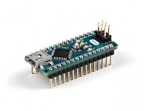
The onboard controller should be light and compact. I chose the Arduino nano form factor (Pic. 1):
1 x Arduino Nano ≈ 22$;
Frankly speaking, I used an analog one:
1 x Iskra Nano Pro ≈ 4$;
To reduce the size, even more, I removed pin headers from the board with cutters.
For the remote control, the size of the controller is not essential. I chose the original Arduino Uno board (Pic. 2).
1 x Arduino Uno ≈ 23$;
The computing power of both controllers is more than enough for the ornithopter controlling task.
Wireless modules.
To create a connection between the remote control and the ornithopter, I need a receiver and a transmitter. Both of these functions can be performed using these boards (Pic. 3):
2 x Mbee 868 version 2.0 ≈ 76$;
I used two boards. First one is a remote control transmitter. The second is a receiver on the ornithopter. These are radio transmitters operating at a frequency of 863-873 MHz, and they can transmit a good signal at a distance of 15 km. With the controller modules communicate using the UART interface.
Servos.
In the ornithopter, the motor is used only for flapping wings. To steer the ornithopter, you need two servos that position the tail. One servo for attitude control (Pitch). Second for turns (Roll). These servos should be light and sturdy. That’s what I chose (Pic. 4):
2 x HITECH HS-65MG ≈ 66$;
These are powerful and fast servos in micro form-factor with a metal gearbox. The only disadvantage is a very rare servo horn format – Micro 23.
In this instructable, I used M23-L and M23-X servo horns with M2 and M1,6 screws. These accessories are included with the servo. However, If the servo horns break, you will have to find a replacement or 3D-print analogs. M23-L and M23-X Hitec servo horns are for the 5mm shaft with 23 tooth spline connection. The horn dimensions are in the attachment.
Posible replacements:
2 x Hitec RCD 35065S HS-5065MG ≈ 70$;
2 x Common Sense RC CSRC-65MG ≈ 40$;
Power bank module.
On the board of ornithopter, all the electronics are powered by a Li-Po battery through the built-in BEC 5V 2A voltage converter on the speed controller (ESC).
But, for the remote control, you need another power supply. I use a 5V 2000 mA power bank module (Pic. 5). It is enough for a relatively long operation of the remote.
1 x Li-Pol Power Bank ≈ 22$;
Input modules.
These are modules that are mounted on the console of the remote control and are driven by hands. I used a Slider potentiometer (Pic. 6) to change the speed of the motor and the frequency of the flaps. To generate Roll and Pitch parameters I used a joystick module (Pic. 7). Similar to what is on the real RC devices.
1 x Slider (Troyka Module) ≈ 6$;
1 x 3D Joystick (Troyka Module) ≈ 7$;
Step 6: Preparation. CNC Cutting.
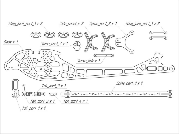
I decided to make fuselage parts of the ornithopter from sheet material with a thickness of 2 mm (Pic.1). These fuselage parts must have a very rigid structure and low weight.
At the development stage, I tried to manufacture parts from different materials such as plexiglass, fiberglass, carbon fiber. To cut test parts made from plexiglass I used a CNC laser machine and CNC milling machine for parts made from fiberglass. Components made of carbon fiber were the strongest. Carbon fiber is a really durable material. But, somehow these parts turned too heavy. Additionally, the carbon fiber is quite expensive.
As for me, fiberglass is the best choice , so I recommend It. Fiberglass parts have good durability to weight ratio. Fiberglass sheets are used by aircraft modellers, and you can find this material in RC stores. Also, fiberglass is a basis for the circuit boards production.
One 1x1m sized sheet is more than enough.
Next is a list of parts that you need to obtain to assemble an ornithopter according to this instruction. The list contains part names and minimum necessary quality.
- Body – 1 piece;
- Servo_link – 1 piece;
- Side_panel – 2 pieces;
- Spine_part_1 – 1 piece;
- Spine_part_2 – 1 piece;
- Spine_part_3 – 1 piece;
- Tail_part_1 – 1 piece;
- Tail_part_2 – 1 piece;
- Tail_part_3 – 1 piece;
- Tail_part_4 – 1 piece;
- Wing_joint_part_1 – 4 pieces;
- Wing_joint_part_2 – 2 pieces;
Step 7: Preparation. 3D Printing.
Some ornithopter parts have a complicated shape and should be very accurate. For example, large gears with many teeth.
In addition to complex shapes, some parts should withstand heavy loads. For example, wing joints have to be durable enough to hold wing rods and to resist wind forces. Custom gears in the gearbox of ornithopter have significant rotating speed, so they should withstand high friction loads.
The easiest way to make them is 3D printing. To achieve accuracy and toughness, I made these parts from the nylon (polyamide) material using the selective laser sintering (SLS) technique. This 3D printing technique is quite expensive, but the result is worth it.
Next is a list of 3D printed parts that you need to obtain to assemble an ornithopter according to this instruction. The list contains part names and minimum necessary quality.
- base – 2 pieces;
- gear_72_t – 1 piece;
- gear_84_t_left – 1 piece;
- gear_84_t_right – 1 piece;
- tail_joint – 1 piece;
- wing_joint – 2 pieces;
The Tail_joint part doesn’t require accuracy and it can be made from ABS plastic using common FDM printing technique.
Step 8: Preapration. Screws, Bearings, Metalware and Other Stuff.
You’ll probably say “What? More components? It is too much =).”
However, the design is very complicated. And to create the same ornithopter according to my instructions you need some more things.
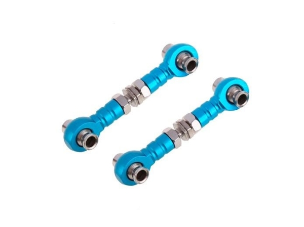
Steering servo links.
You need the steering servo links(Pic. 1) that are used in radio-controlled cars on a scale of 1:10. The link length must be adjustable. The distance between the two ball joints that you need is 43mm.
Here is an example:
4 x HSP 02157 ≈ 20$;
This detail is cool and can be used in many ways. For example, transmit force at an angle. In the ornithopter, I use four such parts.
Two of them transmit the rotational motion from the gears of the reducer to the translational motion of the wings of the ornithopter.
The other two parts are in the tail of the ornithopter and link the fuselage with the cross-section rods which are installed in the wings.
Micro Drill Chunk.
Also you need two small Drill Chunks for a 3mm shaft with 3mm Collets (Pic. 2). Usually such things are used to drill the PCB holes.
Here is an example:
2 x 0.5-3mm Small Electric Drill Bit Collet Micro Twist Drill Chuck Set ≈ 9$;
I used these collars to fix the cross-section rods of the wings with the screw of the servo links. Later, I tried to screw the 3mm carbon fiber rod into the ball socket directly, but such mount was falling apart. It seems that in my design there’s a lot of pressure on this place.
Metal gears.
Some metal gears for the gearbox (Pic. 3): This gears can be tough to obtain, try to find or make a replacement. These parts are necessary!
8 teeth, 2.3mm shaft bore, 0.5 module (48 – 50 pitch)
You need 1 piece. I used this one with 12mm length:
1 x RC Model Metal Pinion Gear 0.5M 2.3mm(hole diameter) ≈ 10$;
9 teeth, 2mm shaft bore, 0.5 module (48 – 50 pitch)
You need 3 pieces. I used this ones:
3 x Pinion Gear 9T (Steel/Micro) 72481 ≈ 12$ each;
Bearings and shafts.
You need some bearings (Pic. 4):
4 x Flanged bearing 4mm х 9mm х 4mm F684ZZ ≈ 9$;
3 x Flanged bearing 2mm x 5mm x 2.3mm FMR52ZZ ≈ 6$;
One stainless steel shaft with a diameter of 2mm and a length of 45mm. You can cut it from this one:
1 x 2mm x 150mm Stainless Steel Model Straight Metal Round Shaft Rod ≈ 8$;
Fasteners.
Screws:
- Screw M2 (DIN 912 / ISO 4762) 10mm length – 9 pieces;
- Screw M2,5 (DIN 912 / ISO 4762) 10mm length – 1 piece;
- Screw M3 (ISO 2342 / ISO 4026) 4mm length – 4 pieces;
- Screw M3 (ISO 7045 / ISO 1207) 6mm length – 6 pieces;
- Screw M3 (ISO 7045 / ISO 1207) 10mm length – 7 piece;
- Screw M3 (DIN 912 / ISO 4762) 20mm length – 2 pieces;
- Screw M3 (DIN 912 / ISO 4762) 25mm length – 4 pieces;
- Screw M4 (DIN 912 / ISO 4762) 16mm length – 1 piece;
- Screw M4 (DIN 912 / ISO 4762) 25mm length – 2 pieces;
- Screw M4 (DIN 912 / ISO 4762) 45mm length – 1 piece;
- Nylon Screw M3 (ISO 7045 / ISO 1207) 8mm length – 13 pieces;
Nuts:
- Hex nut M2 (DIN 934 / DIN 985) – 9 pieces;
- Hex nut M2,5 (DIN 934 / ISO 4032) – 1 piece;
- Hex nut M3 (DIN 934 / DIN 985) – 19 pieces;
- Hex nut M4 (DIN 934 / DIN 985) – 4 piece;
- Nylon Hex nut M3 – 5 pieces;
Washers and standoffs:
- Washer M2 (ISO 7089 / DIN 127) – 9 pieces;
- Nylon standoffs (spacer) M3x10mm – 16 pieces; or M3x20mm – 8 pieces;
Step 9: Design. Gearbox.
How to make a gearbox?
Here I just explain the design. The assembly and the list of gearbox components are shown in the steps below. Look at the sketch to figure out the gearbox design.
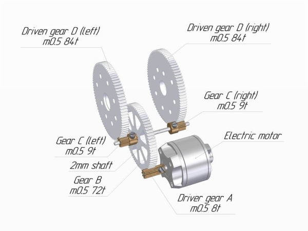
Of course, you need some gears. Since I use a transverse shaft design, I need 2 end-gears (left and right driven D gears) that will move wings up and down. The flapping frequency of wings of my ornithopter is 5-7 strokes per second. This is the speed that these gears should rotate.
To achieve the desired rotational speed, I use 2 pairs of gears (gear A + gear B and gear C + gear D). So it is a gearbox with two stages of reduction. For the first gear pair (gear A + gear B) the transmission ratio is 8:72. For the second (gear C + gear D) ratio is 9:84.
A such number of teeth choice is determined by pinion gears (gear A, gear C) that I managed to find in stores. B and D gears are made using 3D printing, so for them, I could choose any number of teeth. All gears have a module of 0.5.
The driven gear A is mounted to the motor shaft. Gear B left, and right gears C are rigidly mounted on the shaft. So, they have the same rotation speed.
The total reduction is the product of the first stage of reduction and the second stage of reduction. Let’s calculate the total reduction ratio.
(72 / 8) * (84 / 9) = 9 * 9,333 = 84. It means that the total ratio is 1:84.
If the electric motor is powered by 7.4V, the driven gear A rotates 31080 revolutions per minute or 31080 / 60 = 518 revolutions per second. With the total reduction ratio, I can find the speed of end-gears (left and right driven D gears).
518 / 84 = 6.16 revolutions per second.
This value equals the number of wing strokes per second at the 7.4V supply voltage and no load. It lays in the 5 – 7 range I need. If this flapping frequency is high, I will reduce the speed of the engine. If it is low, I will try to raise the voltage using the 3S (11.1V) battery.
Step 10: Assembling. Gearbox.
The material list:
Look at the previous steps for a list purchased components and information on manufacturing parts.
Here is the list of parts you need to assemble the gearbox.
Electronics:
1. 2627 4200KV brushless outrunner motor – 1 piece;
Metal gears:
2. Metal pinion gear (driver gear A), module 0.5, 8 teeth – 1 piece;
3. Metal pinion gear (gear C), module 0.5, 9 teeth – 3 pieces;
3D printing:
4. Nylon gear B, module 0.5, 72 teeth – 1 piece;
5. Nylon gear D left, module 0.5, 84 teeth – 2 pieces;
6. Nylon gear D right, module 0.5, 84 teeth – 2 pieces;
7. Nylon “Base” part – 2 pieces;
CNC cutting:
8. “Body” part – 1 piece;
9. “Side panel” part – 2 pieces;
Bearings:
10. Flanged bearing 4mm х 9mm х 4mm F684ZZ – 3 pieces;
11. Flanged bearing 2mm x 5mm x 2.3mm FMR52ZZ – 3 pieces;
Metalware:
12. Metal shaft 2mm diameter 45mm length – 1 piece;
Screws:
13. Screw M3 (ISO 2342 / ISO 4026) 4mm length – 4 pieces;
14. Screw M2 (DIN 912 / ISO 4762) 10mm length – 3 pieces;
15. Screw M3 (ISO 7045 / ISO 1207) 6mm length – 6 pieces;
16. Screw M4 (DIN 912 / ISO 4762) 45mm length – 1 piece;
17. Screw M3 (DIN 912 / ISO 4762) 25mm length – 2 pieces;
18. Hex nut M4 (DIN 934 / DIN 985) – 1 piece;
19. Hex nut M2 (DIN 934 / DIN 985) – 3 pieces;
20. Hex nut M3 (DIN 934 / DIN 985) – 6 pieces;
21. Washer M2 (ISO 7089 / DIN 127) – 3 pieces;
22. Nylon standoffs (spacer) M3x10mm – 16 pieces; or M3x20mm – 8 pieces;
Assembling process:
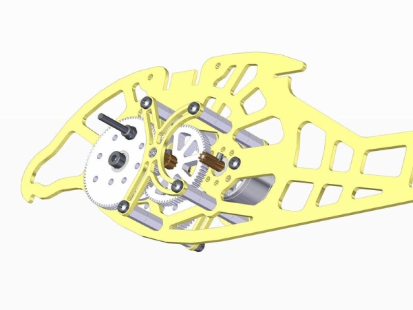
Look at the sketches. They will help you with the assembly.
- Scheme 1. Attach the metal pinion gear (pos. 2) to the motor (pos. 1). Fix it to the shaft using the screw (pos. 13).
- Scheme 2. Take the “Body” part (pos. 8) and insert the bearing (pos. 10). Attach two “Base” parts” (pos. 7) to the “Body” part and fasten them using screws (pos. 14), washers (pos. 21) and nuts (pos. 19). Attach the motor from the first scheme to the “Body” part. Fix it with screws (pos. 15).
- Scheme 3. Insert the 2mm shaft (pos. 12) into the metal pinion gear (pos. 3). Pinion should be at about 24mm to the edge of the shaft. Fix the pinion using the screw (pos. 13). Put the B gear (pos. 4) to the pinion. I made some kind of a splined connection.
- Scheme 4. Take the “Body” part from scheme 2 and insert the bearing (pos. 11). Take the assembly from scheme 3 and put it into the bearing (pos.11). Install two the gears (pos 3) on the shaft and fix them with screws (pos. 13). These gears should be equally oriented and approximately be at the same distance from the “Body” part.
- Scheme 5. Take nylon gears (pos. 5 and 6) and press down bearings (pos. 10) into them. Insert screws (pos. 17) to the gears (pos. 5 and 6) and fix them with nuts (pos. 20).
- Scheme 6. Take the “Body” part from the scheme 4. Mount left, and right assembled nylon gears from the scheme 5 using the screw (pos. 16) and nut (pos. 18). These nylon gears should be symmetrically oriented. Do not tighten the nut (pos. 18) too much. Gears should rotate freely.
- Scheme 7. Press down both bearings (pos. 11) into two “Side panel” parts (pos. 9). Fasten 4 standoffs (pos. 22) on each side of the “Body”. Install both “Side panel” parts to the standoffs using screws (pos. 15) and nuts (pos. 15). Bearings (pos. 11) should fit the shaft that is already installed in the “Body”.
Try to make a high-quality gearbox assembly. If you are going to use some parts or components that differ mine ones, then you should calculate all assembling dimensions by yourself. Try to rotate the motor manually. All gears should turn smoothly without jerks and jams.
Step 11: Wings and Tail. Design and Components.
Design
Ornithopter wings can be flexible or rigid.
Flexible wings are a stretched fabric that forms a membrane maded from lightweight and tear-resistant material. Also, the material mustn’t allow to pass air through.
The rigid wing design is much more complicated. Each cross section of the rigid wing have a real aviation wing profile. This wings require a frame system and accurate geometry. Furthermore ornithopter with a rigid wing is bigger and heavier than I planned to make. So the wing of my ornithopter is flexible.
Fabric
For a flexible wing the best solution is the nylon fabric use. Nylon fabric is also called “Ripstop”. The special reinforcing technique makes this fabric resistant to tearing and ribpping. Nylon fabrics are commonly ised in sails, kites, parachutes and remote control hovercrafts.
At first I drawn a test sketch (Pic. 1) to fiqure out what wings and tail dimensions should be.
I found a piece of blue colored nylon fabric (Pic. 2) in a local kite repair shop. It has 1.5 meters width and 5 meters in length.
Here is an example:
1 x Kite blue nylon fabric 1.5x5m ≈ 33$;
Nylon fabric of this size is enough to make more than one pair of wings. I’m sure you can find such fabric at your local stores.
Rods
The idea is to use nylon fabric as the primary material and strength it with stiffening rods to create tension. These rods form a kind of wing skeleton.
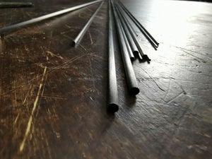
I use carbon fiber rods. Such rods are lightweight, rigid, and very popular among aircraft modelers. I use rods with outer diameter 4mm, 3mm, and 1.5mm (Pic. 3). It’s better to buy many of them. 10 x 1-meter pieces of each size are enough.
Here are examples:
4 x 5pcs Diameter 1.5mm 500mm 19.6″ Carbon Fiber Rods For RC airplane plane DIY≈ 20 – 60$;
4 x 5pcs 3mm Diameter x 500mm Carbon Fiber Rods RC Airplane Pole ≈ 20 – 60$;
4 x 5pcs Diameter 4mm 500mm 19.6″ Carbon Fiber Rods for RC Airplane Plane DIY ≈ 20 – 60$;
Double sided adhesive tape
To fix carbon rods, I glue them to the wings using nylon strips and a thin adhesive tape. I use double-sided polypropylene (PVC) transparent adhesive tape with the 19mm width (Pic. 4).
Note that to follow this instruction you need to find a tape with an exactly 19mm or 20mm width since all wing patterns are drawn just for it. Also, it’s better to use a thin tape one with about 0.2mm thickness. The length of 50 -100 meters is enough.
Here is an example of such tape:
1 x Tesa 4970 White Double Sided Plastic Tape, 19mm x 50m, 0.23mm ≈ 10 – 20$;
Sewing (Optional)
After gluing all rods and strips, for the more reliability, you can sew all joints with threads. So, you need threads, needle or a sewing machine.
Step 12: Wings and Tail. Patches.
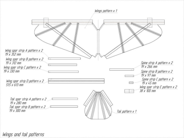
To make wings and tail, you need to cut nylon fabric into some patches of a specific shape. The main surface of the left and right wing is a single cut piece of nylon fabric.
Look at the sketch (Pic. 1) to figure out what fabric patches you need to cut.
The patterns on a scale of 1:1 with real dimensions are in PDF and DWF files in the attachment.
The most significant pattern (the one for both wings) is split into two sheets A1. You can print these A1 sheets separately and then combine.
The A0 sheet contains the tail pattern and patterns for nylon stripes.
Next is the list of all patches you need to cut.
Wings:
- Wings – 1 piece;
- Wing spar strip A (19 x 352 mm) – 2 pieces;
- Wing spar strip B (19 x 312 mm) – 2 pieces;
- Wing spar strip C (19 x 330 mm) – 2 pieces;
- Wing spar strip D (51.5 x 613 mm) – 2 pieces;
- Wing spar strip E (38 x 100 mm) – 2 pieces;
- Spine strip A (19 x 266 mm) – 2 pieces;
- Spine strip B (19 x 97 mm) – 2 pieces;
- Spine strip C (19 x 45 mm) – 2 pieces;
Tail:
- Tail – 1 piece;
- Tail spar strip A (19 x 280 mm) – 2 pieces;
- Tail spar strip B (19 x 300 mm) – 2 pieces;
Source: Opensource Ornithopter Prototype. Arduino Powered and Remote Controlled.