Summary of Open Grow Light
The article describes the development of the Open Grow Light, an open-source indoor plant grow system that simulates seasonal lighting based on latitude and controls moisture and temperature year-round. Starting from programmable RGB NeoPixel LEDs controlled by an Arduino Mega2560 Pro Mini, the system evolved to include sensors, relays, a water pump, heater, fan, and a custom enclosure. It uses multiple Arduino sketches and libraries to manage lighting schedules, moisture levels, and temperature. The system features a laser-cut enclosure, 3D printed parts, and a custom PCB for ease of assembly and reliability, making it ideal for accelerating indoor plant growth.
Parts used in the Open Grow Light:
- 256 NeoPixel RGB LED Panel (options: 8x32, 16x16, or 32x32)
- 5V Power Supply LR550-5
- AC Plug/Cord with 1A Fuse
- 5V Fan
- 5V Water Pump
- Aquarium Tubing
- 2004 LCD Display
- Mega2560 Pro Mini Arduino
- 3 PushButtons (5mm x 5mm)
- 3 Relays (5V DC)
- VA RTC with CR2032 Battery (Real Time Clock)
- Moisture Sensor/Probe
- Dallas 18b20 Temperature Probe
- 10K Potentiometer (12.5mm)
- 3 x IRF510 Transistors
- Screw Adaptors (x2 and x3)
- 40 Female Header Pins
- 40 Male Header Pins
- 4 x 470 Ohm Resistors
- 4 x 1K Ohm Resistors
- 1 x 4.7K Ohm Resistor
- 3 x 100K Ohm Resistors
- 1 x IN4007 Diode
- 1 x 1000uF 16V Capacitor
- 3D Printed parts (spacers, button caps, tubing plug, etc.)
- Custom laser-cut enclosure
- Custom PCB (third revision)

Exactly a year ago (February 2020), James’ wife wanted to expand her plant growing setup in the house.
This included a bigger, larger, taller plant growing area AND the need for more lighting.
BINGO! The seed for the Idea was planted.
After an exhaustive market research, not able to find the product that we had in mind, we started the design of this new amazing device.
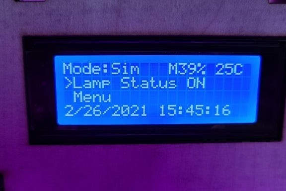
What started as a simple programmable light source has evolved into a full featured Open Source Grow System which you can use to simulate the seasonal lighting condition/duration for any desired latitude and it will also control the moisture and temperature of your growing area year-round.
This allows you to simulate for example, a San Diego, CA spring climate even if you live in New York during winter.
The system has been thoroughly tested and performs even better than expected.
Being Open Source, of course allows you and everyone in the Open Grow Light community to improve and even expand on it.
Step 1: LEDs

OK, I admit we are LED junkies, any project with bright shiny programmable Light Emitting Diodes gets our attention. From our Open Enigma to our Open DSKY, the more LEDs, the better! So how about 256 (or 1024 in our Quad unit) individually programmable RGB LEDs (NeoPixels)!
Oh Yeah! That is the fun part!
However, in today’s world, there are so many options for LEDs, it can be mindboggling to choose the right solution. We knew we wanted individually addressable (NeoPixels) LEDs so we could control each LED brightness and color separately for maximum flexibility.
We knew we wanted 5 Volts for Arduino compatibility.
We experimented with various strips of different densities until we landed on the flexible panels we use. The 8 x 32 panel is ideal for the Kitchen counter herb garden, while the square 16 x 16 is ideal for a bigger area and the quad at 32 x 32 LEDs can light up an even much bigger area.
As you build your unit, you could choose to use instead any strip density of Neopixel 5V RGB LEDs. They don’t need to be waterproof, but it they have an adhesive backing, this may come in handy in your project. Just remember to tell the code how many Neopixels are there to control.
Step 2: Electronics

Our first prototype only had a 1602 LCD with an Arduino Nano and an RTC (Real Time Clock). This Proof of Concept worked like a charm, we knew we were on to something. However, we quickly realized we need a bigger screen, a temperature sensor, a moisture sensor and a water pump. We also added relays to control a heater circuit and a cooling device
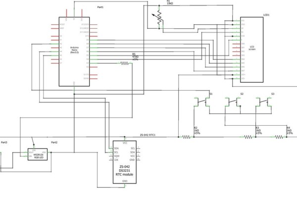
Here is our schematic.
You can use a full size Perma proto board from Adafruit if you want to build a basic unit, however if you desire a full fledge Open Grow System, you will need a bigger platform to fit all components.
Bill of Material to populate your main board (or our PCB):
Qty Item
- 1 2004 LCD
- 1 Mega2560 Pro Mini
- 3 PushButtons 5mmx5mm
- 3 Relay 5VDC
- 1 VA RTC+2032 Batt
- 1 Moisture Sensor/Probe
- 1 Dallas 18b20 Temp Probe
- 1 Pot 10K 12.5mm
- 3 IRF510
- 4 ScrewAdaptorx2
- 2 ScrewAdaptorx3
- 3 40 Female Pins
- 1 40 Male Pins
- 4 470 Resistor
- 4 1K Resistor
- 1 4.7K Resistor
- 3 100K Resistor
- 1 Diode IN4007
- 1 Cap 1000uF 16V
Bill of Material for the enclosure contents:
- 1 256 Neo LED Panel
- 1 Power Supply LR550-5
- 1 AC Plug/Cord w/1A Fuse
- 1 5V Fan
- 1 5V Water Pump
- 1 Aquarium Tubing
We wired the:
- Neopixels on Pin 3
- LCD on (4, 5, 9, 8, 7, 6); //rs,en,d4,d5,d6,d7
- Dallas Temp Sensor (One Wire Bus) on 13
- Heater Relay on 12
- Fan Relay on 11
- Water Pump on 10
- Reed Relay (Moisture) on 2
- Buttons on A2
- Moisture sensor on A3
You can expect all these components to cost you around $150 or more, depending where you get them from, but the end result is an accelerated indoor growth for plants and herbs. Well worth it!
Please note that the Moisture Sensor probe, if left on 24/7 will disintegrate and fail closed because of electrolysis.
Step 3: Code
Coding this thing in Arduino to make it fit on a Nano has been lots of fun, to say the least.
We found out quickly that the Nano does not have enough memory to control 1024 Neopixels.
Once we upgraded to the Mega2560 Pro we are now using, this problem immediately went away. We then were able to add all the functionality we desired.
My favorite part was the season simulation for any latitude on the planet for the whole year. This required to create a sunrise/sunset table (stored in the EEPROM) for the whole year to be used to derive YOUR sunrise/sunset times for YOUR location.
HINT: The sunrise and sunset time for any latitude will fall between the Artic Circle and the Equator.
You will need 3 different Arduino sketches.
First, you need to wipe to zero all locations in the EEPROM using the EEprom_Clear code available @ Arduino.cc.
Then you need to run our DayLenghtSet INO file, which will load the EEPROM with all 365 daylight length durations, required to calculate the sunrise and sunset for anywhere on Earth.
Finally, you need to load our Production code that runs the interface, controls the light and read moisture sensor and starts/stops the water pump based on your desired moisture level.
You will require many libraries if you run the full fledged Open Grow System:
- RTClib.h
- LiquidCrystal.h
- EEPROM.h
- Adafruit_NeoPixel.h
- OneWire.h
- DallasTemperature.h
NOTE: As mentioned in the electronics section, it is important to poll the moisture sensor probe from time to time to avoid electrolysis if kept on 24/7. We tested it and it will die within 1 week if kept on 24 hours a day…
Step 4: Enclosure

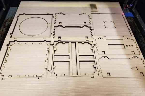
We have evolved the enclosure repeatedly during each iteration of the design process. From the original 1602 LCD barebones unit with the Arduino Nano unit on a proto board to the final Mega2560Pro on our 3rd generation custom PCB, the enclosure has continued to improve. We started with a 3D printed box for the LCD and brain only and moved to a lasercut enclosure for the whole assembly.
The current lasercut enclosures are flexible, streamlined and provide ideal visual appeal while containing the electronics in the minimum amount of space. Special consideration has to be given to air flow.
NOTE: Whenever you combine electricity and water, it is extra important to be careful and keep these 2 elements apart.
Step 5: 3D Printed Parts
Along the process, we needed a few custom parts, so we simply designed and 3D printed them.
- Spacers
- Button caps
- Tubing plug
- etc.
Step 6: PCB

Of course, if you build multiple units, you need a PCB for reliable repeatability. 3 PCB revision later, we have our full featured Printed Circuit Board. Available at a low price, this will cut your headaches and DIY time by a lot!
If you intend to build this awesome educational project, but you are on a budget, this piece alone is probably your best choice.
Source: Open Grow Light
