{This instructable was created in fulfillment of the project requirement of the Makecourse at the University of South Florida (www.makecourse.com).}
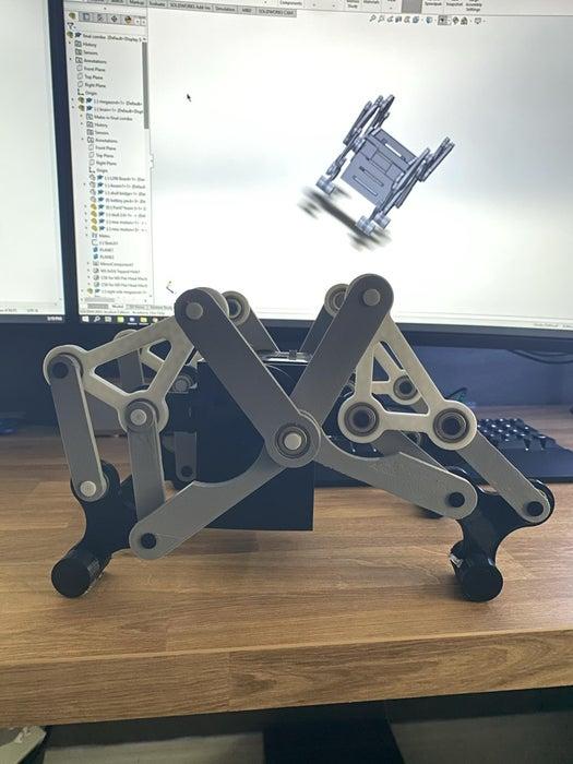
Inspired by the Wind powered machines built by “Theo Janse” I’ve come up with a design of my own, but with a twist. This design houses two 12volt motors to provide the power, an Arduino, and is infrared controlled. Thanks to two individually controlled motors, we are able to change direction with the press of a button.
Supplies
- Arduino Uno
- L298N board
- handful of small M3 and M2.5 screws.
- 2x JGY-370 12V 18rpm motors
- The casing was designed to work with these motors as the locomotion requires a lot of torque, If using other motors with different mounting options make sure to modify casing accordingly.
- https://www.amazon.com/gp/product/B07FD25G6Y/ref=p…
- 4 AA sized LiFePo4 batteries to work as a 12v powersupply.
- 4 AA battery holder(i used one with a power switch which allows for turning off the robot.)
- Universal Infrared Receiver, I used one with an integrated pullup resistor
- about 32 8x22x7mm Ball bearings
- these are used within the joints to minimize friction
- All of the STL files can be found in the .zip file. Instructables won’t let me upload a zip file for some reason, so just delete the ‘.txt’ and it will work as a normal zip file.
Step 1: Soldering
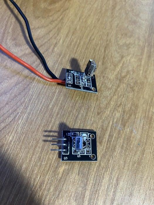
We need to prep our IR receiver and motors to wire directly to our other components.
The IR Receiver has leads that poke out the top, this interfears with how we want it to fit inside our casing, so we’ll star off by taking those off. Heating the solder holding them in place lets you pull them out with ease. After doing that, we want to take some 0.5mm wire, strip the tips bare and feed them into the holes left behind by the leads before soldering them in place. To make it easier use different colors. I used black for ground, red for 5V, and yellow for output.
The motors will need wires soldered onto them as well, I used yellow and red, for both leads.
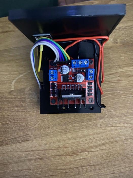
Step 2: Assembling the Circuit Correctly Is Critical
Power
- To make sure all our components are being powered we’ll rely on the L298N board and the battery pack we obtained. The board can take a bit more than 12 volts with no issue, and it also has a 5v step down that we will use to power our Arduino through the Vin pin.
- The four Lithium Iron phosphate batteries will be inside the case as they are the same size as AA batteries. Thanks to each pumping about 3.2V, we get around 12.8 with some minor losses.
- The Arduino will share ground with the L298N board as both will be grounded together with the battery.
- The Infrared receiver will receive power through the 5V pin and be grounded by the second Ground pin in the Arduino.
- The motors will be powered by their designated outputs from the L298N board. If they aren’t both spinning in the same direction when running the forward function, swap the polarity in one of the motors when plugging them into the driver board.
Data
- first off, check to see if your L298N board has jumpers on the ENA and ENB pins, if so, remove them as we can use those to control the velocity of each motor.
- Using a slightly modified ribbon cable we’ll connect all six of the input pins of the L298N board to the corresponding pins in the Arduino. (this cable will have to shorten to limit the amount of excess cabling inside the case.
Step 3: Assembling 3D Printed Parts
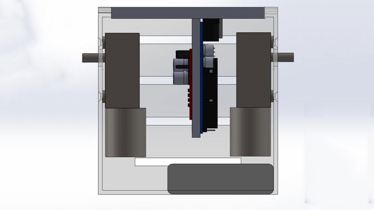
All the components will be housed in the parts called “The Skull.” The motors screw directly into this part and there is a cutout at the bottom to access the power switch in the battery pack.
The “Skull Bridge” is the bracket that the Arduino, the IR receiver, and the L298N board all mount to, this allows for assembling all the wiring before mounting it into the Skull. either double-sided tape or M3 screws can be used to mount the driver board and the Arduino. The hole for the IR receiver is tight enough to stay in place by simple pressure fit.
The rest of the components will need to be attached to the Skull via pressure fitting together as well. I’d recommend fitting the Ball bearings to all the components that require them before assembling the legs.
- place the battery holder in the Skull with the switch poking through the hole in the corner
- Screw motors into both sides of the Skull, Using 2.5M screws with low profile Philips heads is ideal.(can find them easily by looking “Laptop screws”)
- The spine will snap into the ventilation gaps in the Skull housing. Make sure they aren’t being put upside down, (the square hole in the center should line up with the hole in the skull casing and avoid interfering with the Motor shaft.
- the Cam piece will fit into the motor shaft. Tightening it down with a Screw is recommended as to avoid wobbling.
- One of the Joints that connect the Thigh pieces to the Spine on each side needs a Spacer to help align the legs.
- The plug shoot and the plug chug will need to be glued together for final assembly but I recommend laying all the pieces out before gluing anything down.
Step 4: Installing the Code
The code here is optimized for my remote, so make sure to map the buttons of your remote to the functions you’d like. Thanks to the function:
Serial.print(“Unknown command: “);
Serial.println(command, DEC);
break;
Checking the Serial Monitor while having the IR Receiver and the Arduino connected to your computer, you should be able to see what readout each button gets. use that readout to replace the values i have assigned to each function.
The code permits for individual control of both motors and thanks to utilizing functions, any complex functions can easily be constructed via making recalling the prior functions. The Dance function is an example of that:
void dance() {
if (debug)
{
Serial.println(“Lets dance!”);
}
moveRight();
delay(200);
moveLef();
delay(200);
and Thanks to the Unknown command function, new buttons can be decoded and easily mapped to those new functions.
Step 5: Final Thoughts
This project was a lot of fun but has come very far from its initial plans.
- To begin with, the project was meant to remain as lightweight as possible, original motors were heavily stepped down 6volt 10 gram motors. and the skull was much smaller. However the length of the legs meant that a lot of torque was required to lift its own weight. Do to time limitations I went with motors that i was sure would have enough torque to move everything.
- due to getting bigger motors the Skull had to be made much bigger, the previous design had the weight centered on the devise. However with the new design, the battery holder is offset to one side.
- The feet allow for the Strandbeest to move its feet without them sticking uneven to the ground. But they don’t provide the legs with any traction on either hard or soft surfaces. My solution was to add sticky rubber to the inside of the feet as that is the part that is in contact with the ground when pulling or pushing the Strandbeest along. Adding some texture or a sharp bevel along the feet could also work for walking on carpet.
- The design doesn’t really benefit from variable speed control due to the locomotion needing to be synchronized, (either with 0 degrees of variance or 180 degrees of variance between the legs) so the code doesn’t really utilize it. but with some tweaking the code could be used for controlling and RC car or something.
Source: RC Strandbeest