Summary of OLED I2C DISPLAY WITH ARDUINO Tutorial
This tutorial guides electronics enthusiasts on interfacing a 0.96-inch OLED display with an Arduino microcontroller using the I2C protocol. It covers hardware requirements, wiring connections between specific pins, identifying the device address via an I2C scanner code, and installing necessary Adafruit libraries. The guide concludes by demonstrating how to run built-in test examples to verify successful setup and display output.
Parts used in the OLED Display with Arduino Project:
- 0.96" OLED Display
- Arduino Uno / Nano
- Connecting Wires
- Adafruit GFX Library
- Adafruit SSD1306 Library
Hello there! Fellow electronics enthusiasts, I am quite sure we all make some or other projects, as a part of our learning experience or academics. We sure would want to display some data present on our micro-controllers, from sensors or simply display some message, so here is a quick tutorial about OLED displays, in which we will learn how to wire and program a 0.96inch OLED Display with Arduino Microcontroller. so follow up this instructable to understand and display your own Message on a OLED Display.
Step 1: Watch the Video
Step 2: Gather the Material
for this Tutorial, we will require only 3 things.
1. 0.96″ OLED Display https://www.gearbest.com/diy-parts-components/pp_1…
2. Arduino Uno / Nano : https://www.gearbest.com/development-boards/pp_629…
3. Connecting Wires : https://www.gearbest.com/diy-parts-components/pp_2…
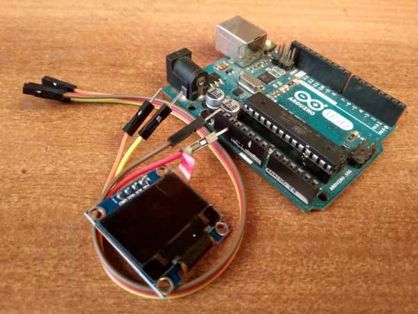
Step 3: Wiring
Since this OLED works on I2C Communication, we have to connect
only 4 pins to Arduino
OLED has Sck (i.e. clock), SDA (i.e. Data) and Power pins i.e VCC and Ground.
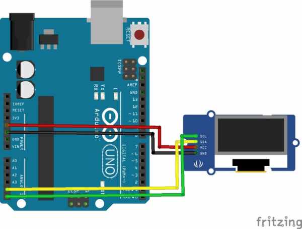
On the Arduino UNO Board, we have SDA at A4 and SCK at A5.
Connections for OLED to Arduino
- Vcc – 5V
- Gnd – Gnd
- SDA – A4
- SCK – A5
Step 4: I2C Scanner
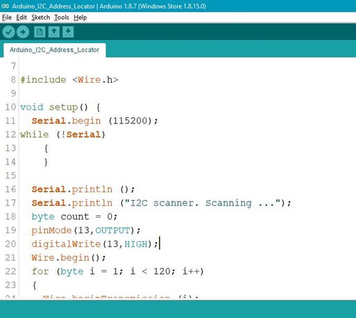
we know each I2C device has different Hexadecimal Address.
since this OLED uses I2C Communication protocol, we have to find the I2C address for the display.
this could be done by uploading the following code onto your board with the device connected.
/* I2C Address Finder
 *  for " Arduino LCD I2C Tutorial| How to Program LCD Display"
 *  subscribe for more arduino Tuorials and Projects

https://www.youtube.com/channel/UCM6rbuieQBBLFsxs...
 */#include < wire.h>
void setup(){
  Serial.begin (115200);
   while (!Serial)
    {
    }  Serial.println ();
  Serial.println ("I2C scanner. Scanning ...");
  byte count = 0;
  pinMode(13,OUTPUT);
  digitalWrite(13,HIGH);
  Wire.begin();
  for (byte i = 1; i < 120; i++)
  {
    Wire.beginTransmission (i);
    if (Wire.endTransmission () == 0)
      {
      Serial.print ("Found address: ");
      Serial.print (i, DEC);
      Serial.print (" (0x");
      Serial.print (i, HEX);
      Serial.println (")");
      count++;
      delay (1);
      }
  }
  Serial.println ("Done.");
  Serial.print ("Found ");
  Serial.print (count, DEC);
  Serial.println (" device(s).");
} void loop() {}
Step 5: Download and Include Libraries
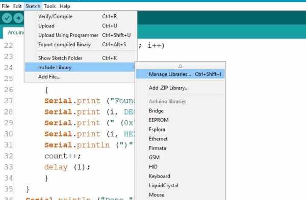
you will need to include the following libraries into your IDE before staring the code.
you can include these libraries by following the steps.
- go to Sketch menu.
- select Include Libraries.
- go to Manage Libraries.
- search for ADAFRUIT GFX and INSTALL it.
- search for ADAFRUIT SSD1306 and INSTALL it.
else, you can install it externally using the following link.
https://github.com/adafruit/Adafruit-GFX-Library
https://github.com/adafruit/Adafruit_SSD1306
Step 6: Testing the Display
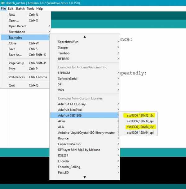
to check if everything works as expected, lets run an example file to test the display.
steps
- go FILE > EXAMPLES > SSD 1306 > Select 128 X 64 i2c
- if you get and Error, try SSD 1306 > Select 128 X 32 i2c
- change the I2C Address on line 61 and replace it with the address you found in step 4.
- upload the code
once uploaded, you will see the test animation on the screen, which means you have successfully set up the oled.
Source: OLED I2C DISPLAY WITH ARDUINO Tutorial
- How many pins are required to connect the OLED to the Arduino?
Only 4 pins are required because the OLED works on I2C Communication. - Which Arduino pins correspond to SDA and SCK for the OLED?
SDA is connected to A4 and SCK is connected to A5 on the Arduino UNO Board. - What is the purpose of the I2C Scanner code?
The code is used to find the hexadecimal I2C address for the display. - Which libraries must be installed before starting the code?
You need to install the ADAFRUIT GFX and ADAFRUIT SSD1306 libraries. - How can you verify if the OLED display setup is successful?
You can upload a test example file from the Examples menu to see a test animation on the screen. - What should you do if you get an error when running the test example?
You should try selecting the 128 X 32 i2c option instead of 128 X 64 i2c or change the I2C Address on line 61. - Does this OLED display use SPI or I2C communication?
This OLED uses I2C Communication protocol. - What voltage should the VCC pin of the OLED be connected to?
The VCC pin should be connected to 5V.