Charlieplexing. Aside from being a fancy word it is a technique for driving multiple LEDs with relatively few pins on a microcontroller. It allows you to drive N*(N-1) LEDs with just N pins without requiring any additional hardware, making it a quick, cheap and easy way to add multiple LEDs to your arduino projects.

Throughout this instructable you will see that I start the majority of steps by directing you to a corresponding simulation. I highly encourage you to play with it before reading contents of the step or looking at images.
To play the simulation, click on “simulate” icon below circuit, wait for it to load and then press “start simulation” above the circuit. Please note that at the time of writing simulation tends to fail to run unless you are logged in due to a bug.
(If you are here just for the “made easy” part of this title, feel free to skip to step 3 or just jump over to step 5 and grab my charlieplexing generator code)
Step 1: Two LEDs
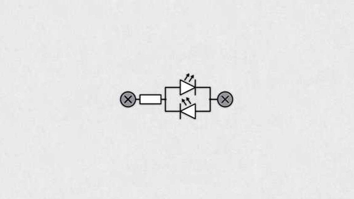
The basic idea behind charlieplexing is best illustrated on example with only two pins and two LEDs. Feel free to play with this SIMULATION – toggle switches and see what happens (switches used in simulation serve to connect middle pin to either + or – ).
If you’re done playing with simulation or you just want a less interactive way of learning, read on.
Unlike standard light bulbs, LEDs conduct current only in one direction. That means that LED will emit light when you connect it “correctly” and act as open circuit when connected “wrong”. If you connect two LEDs in parallel with different orientations, one of the two will shine no matter the polarity. To select which LED shines, you can modulate which pin is + and which – (image 2). If you set booth to either + or -, current won’t have anywhere to flow, turning both LEDs off (image 3).
You have likely noticed that I used only one resistor for two LEDs. That can be done, because electricity “sees” only one LED no matter the polarity. To calculate the resistor’s value, use the standard equation or use this ONLINE CALCULATOR. Keep in mind that max current output from Arduino is 40mA (20mA recommended).
Step 2: Three LEDs
Charlieplexing with two pins is useless. It consumes two pins to drive two LEDs, and takes away the option to turn them both on simultaneously.
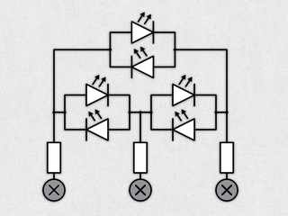
Fortunately it gets a lot better when you add the third pin. Using three pins for charlieplexing allows us to control 6 LEDs. If you intend to play with SIMULATION for this setup, please do it before reading on.
You have seen that as soon as you flip one switch, two LEDs turn on. No matter what you do, either none two LEDs are lit. That is because there are always two LEDs between + and – terminals (image 2).
Solution to this problem is shown in this SIMULATION. You will see that the only difference is that I added three more switches that disconnect terminals. I once again recommend you go through the simulation before reading on.
Newly added switch’s sole purpose is to prevent undesired current flow. Now you can turn on only the LED you want to, but all of a sudden we see ghosting. On arduino, which runs on 5V, ghosting is noticeable when charlieplexing red or green LEDs. That is due to the fact that voltage drop on those two is less than 2.5V and thus some minor current flows through the two LEDs between + and – (image 3). If you were to implement charlieplexing on a microcontroller that runs on 3.3 volts, no ghosting would occur.
Now a word on resistors: Charlieplexing is normally conducted with as many resistors as there are pins for driving LEDs. Value of each resistor is half of the required resistance for driving a single LED the “classic” way.
And to finally address the elephant in the room: I have used three symbols on my schematics: +, – and x. How do they translate to an arduino? + and – are simple. You configure Arduino’s pins as an OUTPUT and write HIGH(+) or LOW(-). Disconnected(x) state is a bit less intuitive. If you configure pin as an INPUT, it goes in so called high impedance mode (high-Z), which means that current can’t flow in or out of that pin, acting somewhat as a disconnected pin. More on that in the step where I talk about Arduino implementation.
Step 3: N LEDs
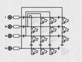
Up until now schematics could have been easily drawn without any intersecting wires. For any more than three pins, that is no longer possible.
You could try to figure out how circuit in the schematic above works, or you could try out this SIMULATION. Note that I omitted switches and an Arduino instead.
You will see that LEDs in the schematic (image 1) are arranged in a NxN grid. Greyed out LEDs are omitted because those would be connected to same pin with both cathode and anode. Anodes (+) of all LEDs in first row are connected to pin1 and so are all cathodes in first column. Other diodes follow suit.
If you are wondering what you could possibly do with such arrangement of LEDs, fear not. This is just a schematic, which serves only for easy wiring. PCB layout can be very different. In this SIMULATION I took the exact same project as before and rearranged LEDs to form a circle (I also changed the code so that LEDs copy potentiometer’s rotation). One more very common use for charlieplexing is in LED cubes – 6 pins allow you to drive 30 LEDs, enough for a 3x3x3 cube while 9 pins are enough for a 4x4x4 version!
Step 4: The Code
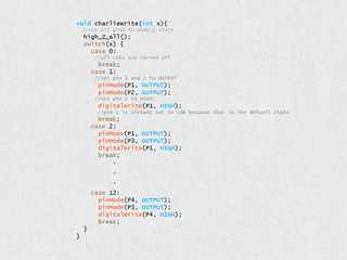
Before showing you how I make the circuits for charlieplexing applications, I would like to talk about the Arduino code for such projects. I will be going through the example with 4 pins, the same code that was used in SIMULATION from previous step. Feel free to play with it and see what happens.
As mentioned before, all pins need to be set to one of three possible states: HIGH (+), LOW (-) and HIGH-Z (unconnected). First two are easy. You configure pins as OUTPUT and use digitalWrite(pin, state) to choose between HIGH and LOW. HIGH-Z (high impedance) is a bit less intuitive, but no more difficult. Whenever a pin is configured as an input, it goes to HIGH-Z mode, which means that the pin can’t sink or source any current.
It is best to start the code by defining which Arduino pin corresponds to which charlieplexing pin. By default all pins are configured as digital input pins, which means they are in HIGH-Z mode.
Next comes the function that configures pins to turn the selected LED on – charlieWrite(led). It first sets all pins to HIGH-Z. That is followed by a SWITCH statement that configures correct pins as correct level outputs. When you configure a pin as a digital output, it is set to LOW by default, which is why I only write level value to the pin I want to be set to HIGH.
Last thing to do is to fill SETUP() and LOOP() functions. SETUP() can be left empty if you don’t need any additional functionality, while LOOP()’s contents depend on desired mode of operation.
In the first DEMO the code is set up to go through all LEDs with a for statement and turns them on sequentially.
Second DEMO is a little bit more advanced. It goes through all LEDs and fakes effect that any number of them are on simultaneously. LOOP() first measures potentiometer value. Through the FOR loop, that measurement is compared to a threshold that corresponds to each LED. If value is above threshold, LED is turned on, otherwise it is ignored. No matter what happened there, a same delay() is called. This ensures that LED brightness doesn’t vary with number of lit LEDs. Note that it would be a lot better to compare “while (micros() – time < 1000){}” would be a better way to go, but I won’t torture the simulator. Attached Arduino code is written properly.
Source: Charlieplexing Made Easy (and What It Even Means?!)