
Summary of Obstacle avoidance Arduino robot – build your own larryBot
This article details the successful creation of larryBot v0.6, an affordable Arduino robot that overcomes previous hardware limitations. The author replaced a low-current H-bridge chip and inefficient motors with higher-performance components to handle stall currents better. The chassis is constructed from cost-effective foamboard using a Tamiya gearbox and track set, allowing for rapid prototyping. The robot runs on 9V power and features obstacle avoidance capabilities using an SRF05 sensor and tank tracks for traction.
Parts used in larryBot v0.6:
- SN754410 H-bridge chip
- Solarbotics RM3 series motors
- Tamiya gearbox 70097 (assembled in mode A)
- Tamiya track and wheel set 70100
- Arduino board
- SRF05 ultrasound distance sensor
- 9v battery
- Foamboard 5mm thick
- Assorted M series nuts and bolts
- Elastic bands
- Breadboard
So after 5 previous versions that had various flaws, I now have an Arduino robot that actually works and although basic is very cheap – although there a probably a few more flaws so please point them out to me but this is a good start on how to make your own robot.
In order to catch up, please see my previous posts below, describing the problems that the other 5 versions had, how the h-bridge chip works and using the SRF05 ultrasound distance sensor.
larryBot – Arduino robot versions 0.1 to 0.5 lessons learned
Control a DC motor with Arduino and L293D chip
Arduino SRF05 Distance Sensor
Now that you’re up to speed, lets start by fixing the flaws in the previous version, this was the case that my motors were drawing way too much current and the L293D chip from ST Micro couldn’t output enough current for each motor.
So, I replaced the chip with the snappy named ‘SN754410‘ from Texas Instruments. This has EXACTLY the same 16 pin layout as the L293D chip and all of the same features except that it can output 1.2 amps per channel rather than the now tiny 0.6 amps of the L293D. Pin configuration diagram below is the same for the L293D as it is for the SN754410, I recommend the SN754410 Arduino comination.
Great I’ve now got more current to my motors, but their stall current is still at over 2 amps, I could add a heatsink to the chip and pass more current through it, but instead I got some more efficient motors than the Mabuchi FA-130’s that came with the Tamiya gearbox. These motors are made by Solarbotics and are their RM3 series which fit perfectly, can handle 4 times the voltage but use a fraction of the current – typically at 9v they use just over 1 amp. Perfect.
Having corrected this, larryBot v0.6 was go! I still faced a lack of power to the DC motors – either because my batteries were running low or not able to supply the current. But since my new motors could run up to 12 volts (instead of the puny 3v of the originals) I decided to use a 9v battery to power them instead of my 4 AA’s.
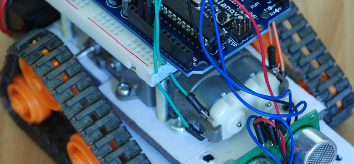
Watching larryBot move is great, even on carpet and with the tank tracks 9 times out of ten he can climb small obstacles or has enough traction to shunt them out the way. Anyway enough waffling – here’s how he’s made…
The Arduino Robot Tracked Chassis
You could use anything you want really – construction sets, your own custom fabricated chassis etc… But since I’m cheap I managed to get a pile of foamboard for my chassis. I can waste and reuse as much of this as I want so its no problem if I make a mistake or want to improve it. Also in theory this leads to rapid prototyping, so when I do decide to fabricate a chassis I know exactly where the best places are for holes, mounts etc…
The robot chassis parts and tools:
Small Phillips/ cross-head screwdriver
Gluegun
Craft knife
Pencil
Ruler
Assorted nuts and bolts – A good set of M series nuts and bolts
Foamboard 5mm thick – 1 A4 sheet is plenty
Tamiya gearbox 70097 – assembled in mode A
Tamiya track and wheel set 70100
Elastic bands (normally dropped by the postie)
Sizing up the robot base
First of all the size of our chassis design is dictated by a few things. The axle length: our tank tracks need about 5mm clearance so the space on the axle is roughly 65mm wide that I can mount on. Next we have the length of the tracks and how many wheels will be used, I kept my track footprint small so my chassis length didn’t need to be much bigger than the gearbox. Which leads on to gearbox positioning – the Tamiya gearbox I have is roughly 75mm in length and the shape of the tracks will dictate where to position the gearbox as the driving wheels are attached to this. The final consideration of course is mounting all the sensors, battery packs, breadboard and the Arduino board.
Read more: Obstacle avoidance Arduino robot – build your own larryBot
- Why was the original L293D chip replaced?
The L293D could not output enough current for the motors, so it was swapped for the SN754410 which handles 1.2 amps per channel. - What specific motors were installed to improve efficiency?
Solarbotics RM3 series motors were used because they can handle four times the voltage while using a fraction of the current compared to the original Mabuchi FA-130s. - How does the new motor configuration affect power supply requirements?
The new motors can run up to 12 volts, allowing the use of a 9v battery instead of the previous 4 AA batteries. - What material is used to construct the robot chassis?
The chassis is made from 5mm thick foamboard to allow for cheap, reusable, and rapid prototyping. - Which gearbox model is utilized in this build?
A Tamiya gearbox 70097 assembled in mode A is used as the driving mechanism. - What clearance is required for the tank tracks on the axle?
The design requires about 5mm clearance on the axle, resulting in a mounting space of roughly 65mm wide. - Can the robot climb obstacles effectively?
Yes, the robot has enough traction with its tank tracks to climb small obstacles or shunt them out of the way nine times out of ten. - What tools are necessary for building the foamboard chassis?
Tools include a small Phillips screwdriver, gluegun, craft knife, pencil, ruler, and assorted nuts and bolts.
