Summary of Nixie Clock Mood Barometer
This article details a DIY project to create an updated analog-display barometer using modern electronics. The author combines a vintage aneroid barometer with a pressure sensor, ESP8266 module, and stepper motor to replicate the nostalgic look while adding useless but functional digital features like Google Assistant control and mood indicators. The project also includes a Nixie clock and chimer mechanism, all integrated via web servers and IoT services.
Parts used in the Analog-Display Barometer Project:
- An aneroid barometer
- A pressure sensor (BMP180)
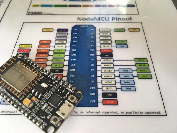
- An ESP8266 module (NodeMCU)
- A stepper motor and driver board
- A 5VDC power supply
- Three LEDs
- An LDR/photoresistor
- Jumper wire, resistors, and heat shrink tubing
An unremarked casualty of Progress is the aneroid home barometer. These days, you might still be able to find examples in the homes of people over ninety, but millions more are in the dump, or on ebay.
In truth, the old-school barometer didn’t help itself by being pretty much useless at its one job. Even assuming it was correctly calibrated and working properly, using atmospheric pressure to predict weather, or even indicate current weather, is almost impossible.
Meanwhile, to supplement the introduction of 24/7 mass media weather reports, super-accurate solid state pressure, temperature and humidity sensors became available. Throw in a processor and a cheap LCD display and you have yourself a “digital home weather station”. Even weather nerds, or people who think weather on tv or the internet is a government plot, didn’t need a barometer any more.
All of which is a shame, because I have warm memories of the barometer we had in my childhood home. My Dad would give it a carefully modulated tap every day and set the current reading indicator in a mini ritual I longed to emulate when I was older, even after I’d figured out the thing was just a world-class blagger.
Here’s how to make an updated analog-display barometer that addresses none of the shortcomings of the original, but has some additional functionality even more useless than what it started out with. If you watch the video, you’ll get the idea.
Given the modest goals of this project, it is quite complex — or more accurately, to replicate the project in its entirety is too much for one Instructable. For this reason, I’ll focus on the barometer/mood barometer portion and for the rest I’ll just point you in the right direction.
Step 1: Ingredients & Tools
For the barometer/mood barometer, you will need:
- An aneroid barometer. Doesn’t have to work. Something that appeals to your aesthetic sensibilities is more important. I wish I had the one from my childhood home but I think it is in the dump. I got a replacement on ebay for $15.
- A pressure sensor.
- An ESP8266 module — I used a NodeMCU.
- A suitable stepper motor and driver board — the link is to a job lot of five but for the price they are hard to beat. This motor has 4096 steps in a complete rotation, giving ample resolution for our purposes.
- A 5VDC power supply — at least 1A — for the ESP8266 and the motor. I used a combined 12VDC and 5VDC supply because I already had one and needed a 12V supply for the Nixie clock (plus more 5V power for the other elements of the project).
- At least three LEDs (to indicate the pressure trend).
- An LDR/photoresistor.
- Miscellaneous consumables such as jumper wire, resistors, heat shrink tubing, etc.
- In most cases, you could use the original case of the barometer you are using to house the electronics. I repurposed a vaguely Arts & Crafts-style clock case to house both the clock and barometer so didn’t need the barometer case.
Toolswise, you’ll need a soldering iron, heat gun and some small hand tools. If you need to make significant modifications to the case, a selection of power tools will come in handy.
Step 2: Prepare Your Enclosure, Carefully
What you need to do here is largely dependent on the enclosure you are using. If you are using the barometer’s own case, you’ll just need to figure out how to get it apart and remove the aneroid mechanism. The pointer is likely directly mounted on this mechanism and some care needs to be taken to detach the pointer without damaging it.
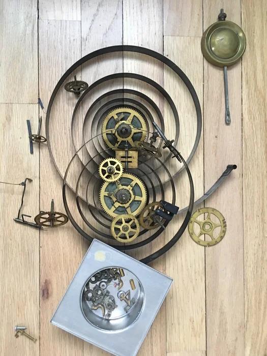
I had a little more work to do, because my clock case still had the old (non-working) clockwork mechanism in it.
I know next to nothing about mechanical clocks, but the beefy coiled springs suggested that I should proceed with caution. Nevertheless, when the thing exploded I was, well, unprepared. One second I was undoing a seemingly inconsequential screw, the next there was a loud bang and the air filled with dust and debris. Bits of clock were all over the place and the case itself was completely blown apart. Much like I imagine when a real bomb goes off, for a moment I couldn’t figure out what had happened. In the deafening silence that followed, I half expected to hear the distant wail of sirens. Also, my hand really hurt.
Lesson One: Even modestly-sized clock mechanisms can store a surprisingly large amount of energy.
Lesson Two: When in doubt, wear safety glasses! I was lucky, nothing flew into my eyes but it certainly could have. Sometimes merely engaging the old safety squints isn’t enough (not even sure I did this). My hand was fine, I was just being a baby.
After a lot of gluing and clamping, I got the case back together and was ready to proceed to Step 3.
Step 3: Install Components — Part 1
You need to find some way to install the motor so the shaft protrudes through the dial just enough so when the pointer is attached it will sweep across the face without interference. This might be a little more difficult than it first appears because most barometers will have another pointer on the inside of the glass which in olden times was used to record the current reading. As explained later, we will not need this pointer but keeping it helps preserve the original look and feel of the device.
In any event, the existence of the current-reading pointer means there is a limit on how far the “primary” pointer can sit off the face of the dial.
In the other direction, the pointer needs to sit away enough from the dial to just clear a washer that will frame an LDR installed into the dial (see next step).
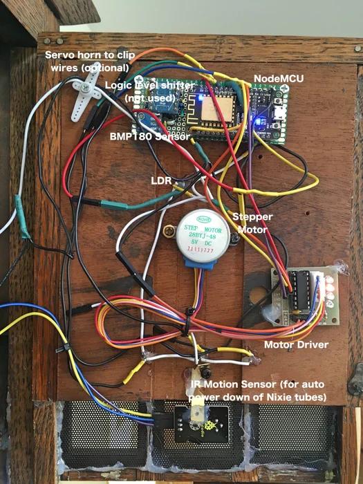
What I did was mount the dial and its frame on a wood backer, then mount the motor on the backer with appropriate spacers. The first picture might help explain this but you may come up with your own arrangement.
One advantage of using a clock case or something similarly-sized is that there is room to install the power supply internally. For me, this was important because the clock was going to sit on a mantelpiece plugged into an outlet I’d installed specially. Hiding an obviously anachronistic “wall wart” or SPS brick in this location would have been difficult — but that might not be an issue for you.
Components not labelled in the second picture relate to to the clock and chimer portions of the project (the third NodeMCU and associated wiring is under the Nixie PCB).
Placement of everything else – primarily the BMP180 sensor, the motor driver board, and the NodeMCU – is not critical. That said, until I routed the interconnect wire away from the driver board the motor sometimes didn’t work properly. Not sure what was going on there but if your motor sounds funny and/or doesn’t move smoothly you might want to try moving the wires around.
To avoid the need to manually record the pressure trend (rising, falling or steady) I included three small LEDs below the dial. When all three are lit, the barometer is in mood mode. I used “warm white” LEDs to try and maintain the period feel. Unmodulated, they were far too bright when viewed head-on but with some heavy-duty PWM I got the look I was after. The current reading pointer is still available for traditionalists.
Step 4: Install Components — Part 2
Let’s deal with the LDR in the dial. First, why the heck do we need this?
Well, it is my solution to a limitation of a cheap stepper motor – although it can move in precise steps, it has no inherent ability to know where it is other than by reference to its starting position. While in theory I suppose you could hard code this and keep track of all subsequent movements I guessed (with no real basis) that errors would quickly creep in, especially given the large-scale movements required in “mood mode”. Also, you’d be stuffed on a power cut (writing each movement to EEPROM is not really practical).
My first thought was to introduce a calibration cycle on power-up and shifts between mood and barometer mode. This cycle would trip a microswitch at a known point on the dial. But the mechanical implementation of the switch idea seemed too challenging for me. The pointer itself is way too flimsy to be the actuator so I’d need to install something else on the shaft. Then there was the issue of preserving 360° motion – one reason I’d gone with a stepper motor rather than a standard servo. With the application of a bit more ingenuity than I could bring to bear I’m sure a microswitch could be made to work — or perhaps there is an off-the-shelf position sensor solution available too — but I went another way.
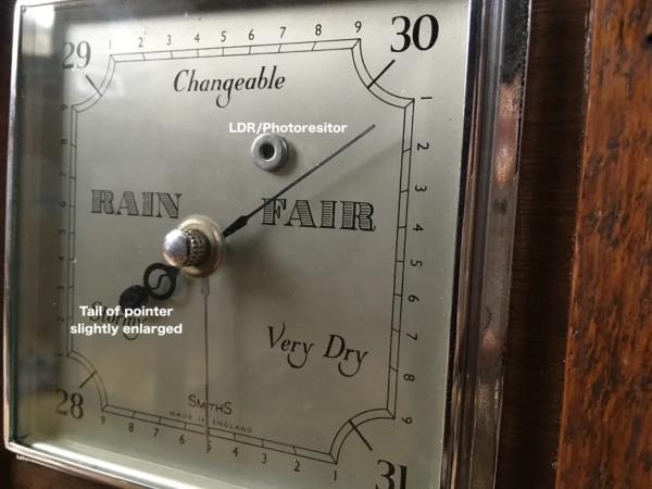
Notice in the picture of the dial there is a washer mounted in the one o’clock position. This washer frames an LDR connected to the single analog input available on the NodeMCU. When the barometer is powered up, or switches modes, the NodeMCU enters a calibration cycle and simply looks for a sudden change in light level caused by the rear of the pointer traveling over the LDR. Any further movement is indexed from that known position. I had to fiddle a bit with threshold values in the code to get this to work reliably but once that was done I was pleasantly surprised at how accurate it was – consistently returning to barometer settings within 1% or 2% of expected values.
It doesn’t work in the complete dark, obviously, but you wouldn’t usually be switching modes then. If for some reason the calibration cycle can’t be completed within a set time, it gives up and flashes the trend LEDs.
Anyway, the beauty of the LDR approach is that installation is super simple – drill a hole just big enough for the LDR in the dial at a point where it will be covered by the back end of the pointer. To get a nice “seal” between pointer and the LDR, glue a small washer round the LDR and, if necessary, modify the pointer tail (i used some suitably shaped black paper).
Step 5: The Code – Basic Functionality
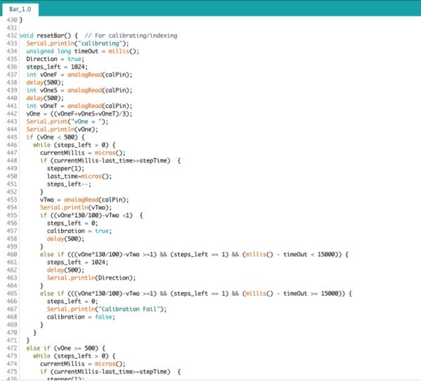
As others have found, I couldn’t get the standard Arduino stepper motor library to work with this motor and driver. Fortunately, there is a good Instructable on this with code that does work. I used the code in the original posting for the basic stepping although there are several optimization suggestions in the comments. This code doesn’t require a library.
For processing the pressure data, I used an example from the Sparkfun BMP180 library. All I had to do then was marry up this with the motor control.
Step 6: The Code – Calibration, Control, GUI, Google Assistant and Utility Functions
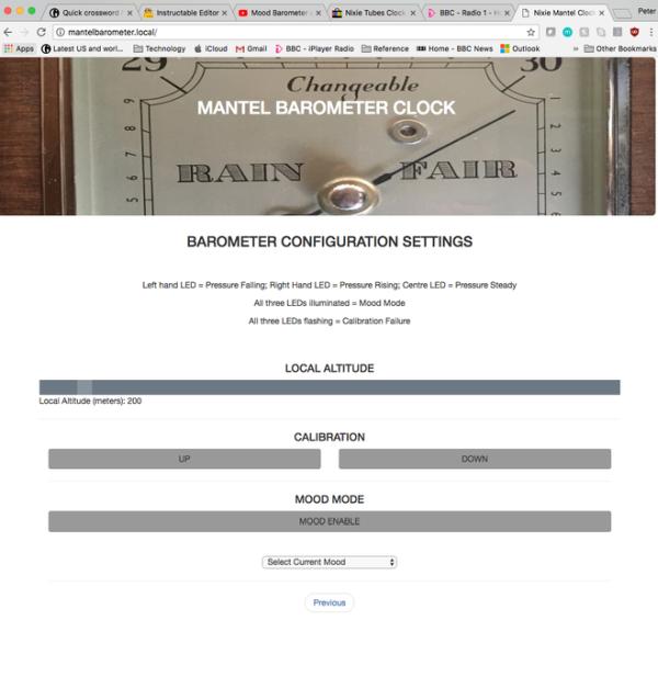
Primary calibration is hard-coded. To be on the safe side, and to account for possible relocation of the barometer to a different altitude, secondary calibration and control is achieved with a web server spun up by the NodeMCU and Websocket communication. A good resource for learning about this is here.
As the video demonstrates, however, the real “wow” factor of this project, such as it is, is control via Google Assistant/Google Home. There is an Instructable for the toaster GA (powered by a Raspberry Pi3) here. Don’t worry, you don’t need to use a $400 toaster as an enclosure.
Commands are passed by the GA via IFTTT and Adafruit IO to the NodeMCU. A good resource on this is here. There are other, more complicated, ways to interact with your Google Assistant but for this project this very simple approach works perfectly.
Finally, the code includes some extremely useful utility functions (over-the-air updating, Multicast DNS, Wifi Manager) that I’ve started to include in all my ESP8266-based projects.
All the code for this project (including the Nixie clock and chimer control) is on Github here. I’ve left the images I used in the HTML/CSS files so it works out of the box (hopefully) – you’ll just need to add your own Adafruit IO account details.
Step 7: The Nixie Clock and Chimer
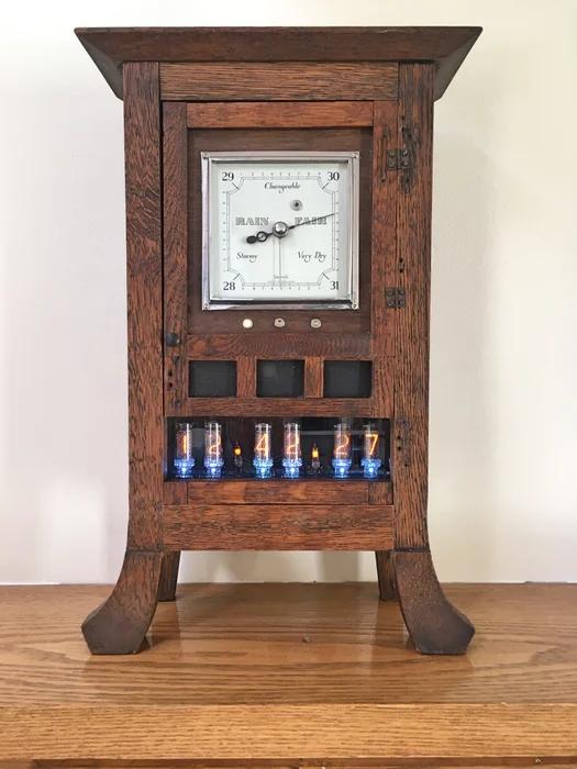
The Nixie Clock is controlled by a separate NodeMCU and uses a Nixie tube and driver module designed as an Arduino shield available here. The version in the link includes a GPS module for obtaining time. My shield (an earlier version) does not have the GPS module but I use the Node MCU to obtain time from the internet, which in some ways is better.
The control scheme and GUI for the clock has more configuration options but otherwise is very similar to the barometer. There is a little overlap here in that the Nixie LEDs respond to mood inputs of the barometer (via the same Adafruit IO feed).
From the wreckage of the original clockwork mechanism I salvaged enough bits to build a chimer mechanism driven by a third NodeMCU (hey, they are only $6 each) and another stepper motor. All I added was an “interface” between the original mechanism and the motor. “Interface” is in quotes because it comprises only of a bullet connector with two nails driven into it at right angles and shoved onto the motor shaft. Each quarter rotation of this contraption results in one strike of the chimer. Once again, the chimer control scheme is similar to the barometer and all three web servers are linked together to make the whole lot seem more seamless than it really is.
The clock and chimer NodeMCUs work completely independently of each other but because of the wonders of internet timekeeping are always perfectly in sync.
Source: Nixie Clock Mood Barometer
- How can I determine the pointer's position without a microswitch?
The system uses an LDR installed in the dial that detects a sudden change in light when the pointer passes over it during a calibration cycle. - Can I use the original case of the barometer for this project?
Yes, in most cases you could use the original case to house the electronics if it fits the components. - What is the best way to control the device remotely?
You can control the device via Google Assistant using commands passed through IFTTT and Adafruit IO to the NodeMCU. - Does the project require a specific library for the stepper motor?
No, the standard Arduino stepper motor library did not work; the author used custom code from another Instructable that does not require a library. - How does the device handle power cuts regarding position tracking?
The LDR calibration method allows the device to find its known position on startup or mode switching, avoiding the need to write movements to EEPROM. - What safety precaution should be taken when opening old clock mechanisms?
You should wear safety glasses because mechanical clocks can store large amounts of energy and may explode unexpectedly. - How are the three trend LEDs utilized in the project?
The LEDs indicate the pressure trend, and when all three are lit, the barometer is in mood mode. - Where can I find the complete code for this project?
All the code including the Nixie clock and chimer control is available on Github.