Summary of Water Level Indicator
This project builds a three-level water tank indicator using an Arduino, a water level sensor, three LEDs (red, yellow, green), and a buzzer. LEDs indicate empty, low, half, and full states; the buzzer sounds when full. The system teaches basic circuit assembly and has industrial uses like sump monitoring, leak detection, and fuel/ liquid-level sensing.
Parts used in the Water Level Indicator Project:
- Arduino Uno
- Water level sensor module
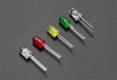
- Red LED
- Yellow LED
- Green LED
- Buzzer
- 220-ohm resistors (one per LED)
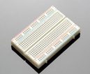
- Breadboard
- Connecting wires
Summary
In this project, we will create a water level indicator with three levels inside a tank using an Arduino and a water sensor, as well as three LEDs and a buzzer to indicate when the tank is full.
Objectives
- To understand how a water indicator works
- When the circuits indicate that the tank is half full, take the water level.
- To learn how to construct simple structures
Industry-Based Applications
Water level indicator circuits are commonly used in factories, chemical plants, electrical substations, and other liquid storage systems. This simple system can be used for a variety of purposes, including monitoring a sump pit (to control pump activation), rainfall detection, and leak detection. Electronic water level circuits can detect if there is a water leak somewhere in the factory. When the water level is too high, too low, or exceeds the upper limit, an alarm sound or different colors of a light bulb can easily detect the water level. We can also measure the fuel level in automobiles and liquid-level containers, which are common in businesses.
Project Methodology
The circuit is set up to show three levels of water in the tank: low but not empty, half and full but not overflowing. All of the LEDs turn off when there is no water in the tank, indicating that the tank is completely empty. When the water level rises and comes into contact with the sensor, the Red LED illuminates, indicating that there is water in the tank. Yellow LED will light up as the water level rises and reaches half the tank. When the water level in the tank reaches full, the buzzer sounds an alarm to indicate that the tank is full.
Components:
- Arduino Uno

- Water level sensor module

- Light-emitting diode (LED’s)
- Buzzer

- Connecting wires

- Breadboard
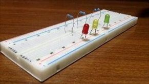
Step 1: Assemble LED on the Breadboard
Red Colour: (indicating extremely low level)
Yellow Colour: (indicating half water level)
Green Colour: (indicating full water level)
- Connect the cathode of each led to the breadboard’s power rail (blue rail), which will serve as the ground supply.
- Connect the LED anode to various nodes.
- Connect a 220-ohm resistor to each LED in series.
Step 2: Connect the Arduino and the LED Connect the LED to the Arduino’s digital pins as shown below:
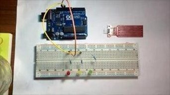
- Red LED wired to Digital to pin 13.
- Yellow LED wired to Digital to pin 12.
- Green LED Wired to Digital to pin 11.
Step 4: Connect the Water Sensor with Arduino
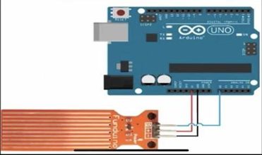
Connect the water level sensor to Arduino in the following manner:
You must connect the Water Sensor pins to the Arduino pins. The Negative (-) pin will need to be wired to the Arduino’s GND. The (+) pin must be connected to VCC on the Arduino, and the (S) pin must be connected to A0 on the Arduino using the wires provided.
Step 5: Connect Buzzer
Connect the buzzer’s positive to Arduino’s Digital Pin 8 and its negative to the ground on the board.
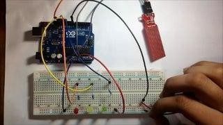
Below is a video with more information and visuals:
After assembling all of the components on the breadboard and connecting them to the Arduino, students will place the water sensor in the empty tank and slowly pour water into it.
Here is Code: https://duino4projects.com/wp-content/uploads/2022/11/Water-level-Indicator-With-Sensor.txt
- How does the project indicate different water levels?
Red, yellow, and green LEDs light at low, half, and full levels respectively, and the buzzer sounds when full. - Can the system detect an empty tank?
Yes. All LEDs remain off to indicate the tank is completely empty. - What Arduino pins are used for the LEDs?
Red LED to digital pin 13, yellow LED to digital pin 12, and green LED to digital pin 11. - How is the water sensor connected to the Arduino?
Connect sensor GND to Arduino GND, VCC to Arduino 5V, and S (signal) to analog pin A0. - Which pin is the buzzer connected to?
The buzzer positive is connected to digital pin 8 and negative to Arduino ground. - Are resistors required for the LEDs?
Yes. A 220-ohm resistor is connected in series with each LED. - What is the intended educational objective of the project?
To understand how a water indicator works and learn simple circuit construction while measuring water levels. - What applications does the article mention for water level indicators?
Uses include factories, chemical plants, substations, sump pump control, rainfall detection, leak detection, and fuel or liquid-level measurement.