This guide will take you through the steps to build an NES playing robot
You will need:
An Arduino Duemilanove (other boards will probably work, but you will have to adjust the steps for your device)
Working NES Console
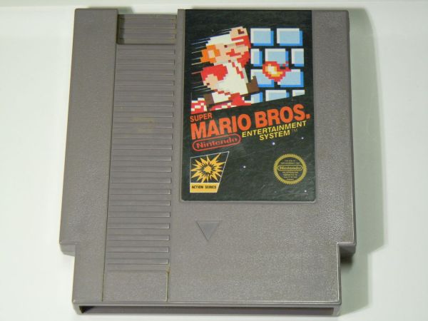
Super Mario Bros. (Note: this must be only the single game, not the two- or three-in-one cartridge)
A controller you can cut the cord from
Two LEDs (two different colors are recommended but not required)
2x ~390 ohm resistors
3x 1.6k ohm resistors
3x 3.3k ohm resistors
4021 (16 pin Shift Register. Note: the 74xx series will not work)
SD Card slot (more on this later)
A pushbutton (not required, but recommended)
A switch (not required, but recommended)
A soldering iron (you’ll probably need one)
Multimeter
Hookup wire

Software needed:
Arduino Interface, available from http://arduino.cc/
Processing, available from http://processing.org/
FCEUX, available from http://fceux.com/ (you probably want the windows binary unless you know what you’re doing)
Step 1: Background information
This project is based off the efforts of the people at TASVideos . For a full description of what they do, take a look at their Welcome Page .
Every approved submission (called “movies”, even though they contain no audio or video data) on their website is simply a series of recorded button presses that in theory can be played back on the actual console for which they are intended. In most cases however the emulator differs too greatly from the actual consoles to make this possible, but in the case of the NES the difference is significantly smaller.
The game choice also makes a big difference as to whether the button presses can be played back or not. If the game relies on any uninitialized memory for randomness, or if it is heavily based on console timing, it may not work. In the case of Super Mario Bros however, as long as the button presses start play back at the right time, the movie will play back correctly.
These button presses are based on frames on the console. Almost every time the console redraws the screen (~60 times a second), the controller is polled for input. However, there are times when the screen is redrawn, but the controller is not polled. These are called lag frames. Due to the difference in the way the emulator handles these lag frames, any movie must be modified to run correctly on the console. This is handled later on.
To turn “in theory” into reality, we will start by modifying the controller.
Step 2: Modifying the Controller
We need to cut the cable on the controller and make it possible to plug it into the schematic on the next step, but we also need to identify the wires inside to make sure they are plugged in correctly.
If you’re lucky (like I was) you can open your controller and the 5 wires will be labeled inside.
If you’re not as lucky you’ll need to do a bit more work. If you opened your controller to check for labels, keep it open, and get your multimeter. Probe each wire inside the controller and on the console end of the wire. Use this picture to find the GND, +5, Data Out, Clock, and Latch wires. Note that the picture is of the socket, so you’ll need to mirror it when looking at your cable.
Once you know which wires are which, cut the controller away from the cable, strip the cable. You’ll need a way to plug these wires into your breadboard. Since these wires are usually small and delicate, I recommend soldering a piece of hookup wire to each. You can also wire each to a line of pin headers like I did. I also modified my controller to have pin sockets which allow me to plug the cord back in and still use the controller.
Once these are able to be plugged into a breadboard, you are ready to wire the rest of the system.
Step 3: Wiring the schematic
Wire the schematic as shown. I recommend doing this on a breadboard. And remember this schematic is based on the Arduino Duemilanove when looking at the pin numbers on the left.
For the SD card, I used a microSD card with a converter that made it into a full sized SD card. I soldered pins onto the converter making it possible to plug it into a breadboard. However you do it, make sure you take note of the pin numbers on the card and wire them correctly.
The pushbutton and switch are not required. If you don’t have any handy just use hook up wires that you connect to ground when you want to “push” them, and unplug them when you’re done. We will be using the pullups built into the arduino, so none are needed externally.
Note that the grounds from both the arduino and the NES are tied together. Also that the 4021 IC gets power from the NES, not the arduino.

If you are modifying this to work on another device, the NES LATCH signal MUST go into an interrupt input. Also the SD card must be connected connected to the SPI interface. For more information that, read here, namely the “Physical Connections” section, and substitute your correct pin numbers. Also note that I left pins 0 and 1 on the arduino disconnected. These are for TX/RD to the computer, and will need to be disconnected every time when programming the device, so I worked around them completely.
Working NES Console
Super Mario Bros
For more detail: NESBot: Arduino Powered Robot beating Super Mario Bros for the NES
