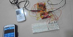
By this mobile controlled automation using Arduino you can perform switching operation of any load or device which is connected with the circuit. Before some days i posted about DTMF tone in mobile communication. Here i am using DTMF tone in this project. Visit following link for more information regarding DTMF.
Suppose you are outside from your home or office and you forget to off any load like tube light, fan or air condition. Hence to switch it off you have to go back there and turn it off. But if you have installed this system in your office or home you can switch off that device right from where ever you are. In other circumstances suppose you want to turn on water pump or irrigation motor then you can also do it from anywhere. You can connect such type of six devices. Circuit Explanation
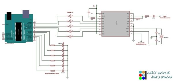
Circuit uses Arduino board ; i have tested this project on Arduino uno and Arduino duemilanove, MT8870 DTMF decoder IC, 74LS04 inverter gate IC and some distinct component. You can download code and circuit diagram from link given at the end of this post.
Heart of the system is DTMF decoding section. To retrieve DTMF code from MT8870 DTMF decoder IC based on DTMF tone provided by the mobile phone connected to it is very difficult and crucial task. So I recommend you to visit above link regarding Dual tone multiple frequency for betterment.
Mobile phone is connected to MT8870 DTMF decoder IC through headphone or aux cable (I am using 3.5mm aux cable) which will transfer DTMF tone to MT8870. Based on received DTMF tone MT8870 IC gives DTMF code as an output. DTMF code is of 4 bit in size. MT8870 has four pins Q0 to Q4 which indicates DTMF code.
However this pin’s output voltages are not stable hence for better and accurate operation 74LS04 inverter gate IC is used. Output of 74LS04 is fed to the digital pins 8 to 12 of arduino. Pins 2 to 7 are connected with LEDs. Here I am using only LED for demo purpose but if you want to connect high voltage device or load than you have to use relay with some driver arrangement.
Project Explanation
After assembling circuit you are ready to use it.. Connect one mobile phone to circuit using headphone or 3.5mm aux cable as I mentioned above. Now power up circuitry. Call from another phone to the phone which is connected with the circuit. Phone which is connected with the circuit must be in auto answering mode. So after some time when call is connected or answered by the phone you can perform switching action.
You have to follow certain input pattern to perform device switching. First of all you have to select device or load using number one to six for this purpose press key 1 to 6. After selecting device or load you can make it on by pressing ‘#’ key and you can make it off by pressing ‘*’ key. If you want to turn on or off all connected devices use ‘0’ to select all device and use ‘#’ or ‘*’ for turn them on or off respectively. Watch video provided at the end for clarification. In Short…
- Select device by pressing key 0 to 6
- To turn on device press ‘#’ key followed by device number
- To turn off device press ‘*’ key followed by device number
Code Structure
MT8870 has one pin called ‘std’ which indicate new valid DTMF code is decoded that means when any valid DTMF tone is applied to MT8870 as an input, it process on it and based on that output latch is modified. DTMF code output pins that is Q1 to Q4 are directly connected with this internal latch. Hence when ever any new DTMF code is generated ‘std’ pin goes high for very small amount of time and return back to normal low state.
For more detail: Mobile Controlled Automation Using Arduino
