
Summary of MCU based LED Arduino VU Meter
This article describes building a modern VU meter using microcontrollers (MCUs) to replace obsolete analog chips like the LM3914. It highlights MCU advantages such as built-in ADCs, fast processing for multiplexing, and PWM capabilities. The author details selecting an MCU with specific features (ADC, ports, timers, interrupts) and demonstrates code flexibility for supporting 6–16 segments across various LED counts.
Parts used in the MCU-based VU Meter:
- Microcontroller Unit (MCU)
- Built-in Analog-to-Digital Converter (ADC)
- Timer Interrupt
- LEDs (segments)
- Multiplexing lines
- PIC16F684 or PIC16F690
- Random number generator (for simulation)
From time to time, I see people trying to build an audio VU meter. In the analog era, that’s typically done with a voltage divider + a series of comparators; or using chips like LM3914/3915.
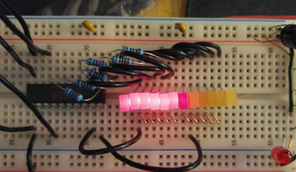
Those chips are harder and harder to find, or you may need more resolution, or a different output profile. What to do?
Modern MCUs offer an easy solution.
- their build-in ADC (10-bit or more) is more than enough for this type of applications;
- their fast speed allows easy multiplexing so a few pins can control lots of output;
- their PWM capabilities also allow them to drive analog coil meters.
In this post, we will explore #1 and #2 and leave #3 to those of you who want to explore more on their own.
Picking a MCU:
For the purposes of this application, we need to pick a MCU with built-in adc, and sufficient pins. Because we are using multiplexing, we also want to control the timing via a timer interrupt. So a mcu with the following features is needed:
- built-in adc;
- port operations;
- timer;
- interrupts.
That’s pretty much any modern MCU, :).
When I started coding for this project, I had a PIC16F684 in my mind, and I thought to pick 6 output pins (“segments”) over 4 multiplexing lines (“digit”, or “channel”) for one adc input, making it a VU-meter driving up to 24 leds. But to make the code more versatile, I decided to write one that supports 6 – 16 segments, 2 – 4 digits so it is good for a total of 12 – 64 LEDs, over 1 or 2 adc channels.
I actually didn’t find a PIC16F684 in my part box so instead I wrote it for a PIC16F690 – but I only used a few pins and used a random number generator so simulate the adc for demo purposes.
Basic Principles of Operations:
Essentially, we are going to take the adc input – in this case, 10-bit adc, and convert it to a 12-bit logarithmic value to be displayed on the LED. For flexibility, I want to support both bar patterns and dot patterns.
The code is written so that each output pin is individually configurable:
//hardware configuration
#define NUM_OF_SEGS 6 //number of segments.

#define SEG0_PORT PORTC
#define SEG0_DDR TRISC
#define SEG0 (1<<0)

#define SEG1_PORT PORTC
#define SEG1_DDR TRISC
#define SEG1 (1<<1)

#define SEG2_PORT PORTC
#define SEG2_DDR TRISC
#define SEG2 (1<<2)

#define SEG3_PORT PORTB
#define SEG3_DDR TRISB
#define SEG3 (1<<4)

#define SEG4_PORT PORTB
#define SEG4_DDR TRISB
#define SEG4 (1<<5)

#define SEG5_PORT PORTB
#define SEG5_DDR TRISB
#define SEG5 (1<<6)

#define SEG6_PORT PORTB
#define SEG6_DDR TRISB
//#define SEG6 (1<<6)

#define SEG7_PORT PORTB
#define SEG7_DDR TRISB
//#define SEG7 (1<<7) //uncomment if not used

#define SEG8_PORT PORTB
#define SEG8_DDR TRISB
//#define SEG8 (1<<0) //uncomment if not used

#define SEG9_PORT PORTB
#define SEG9_DDR TRISB
//#define SEG9 (1<<0) //uncomment if not used

#define SEG10_PORT PORTB
#define SEG10_DDR TRISB
//#define SEG10 (1<<0) //uncomment if not used

#define SEG11_PORT PORTB
#define SEG11_DDR TRISB
//#define SEG11 (1<<0) //uncomment if not used

#define SEG12_PORT PORTB
#define SEG12_DDR TRISB
//#define SEG12 (1<<0) //uncomment if not used

#define SEG13_PORT PORTB
#define SEG13_DDR TRISB
//#define SEG13 (1<<0) //uncomment if not used

#define SEG14_PORT PORTB
#define SEG14_DDR TRISB
//#define SEG14 (1<<0) //uncomment if not used

#define SEG15_PORT PORTB
#define SEG15_DDR TRISB
//#define SEG15 (1<<0) //uncomment if not used

#define CH0_PORT PORTC
#define CH0_DDR TRISC
#define CH0 (1<<7)

#define CH1_PORT PORTB
#define CH1_DDR TRISB
#define CH1 (1<<7)

#define CH2_PORT PORTA
#define CH2_DDR TRISA
//#define CH2 (1<<4) //uncomment if not used

#define CH3_PORT PORTA
#define CH3_DDR TRISA
//#define CH3 (1<<5) //uncomment if not used

//end hardware configuration
The output is written so it can be active high or active low:
Read more: MCU based LED Arduino VU Meter
-
Why are traditional analog VU meter chips difficult to use?
Chips like LM3914/3915 are harder to find, may lack sufficient resolution, or offer different output profiles than needed. -
What advantages do modern MCUs offer for this project?
Modern MCUs provide built-in ADCs of 10-bit or more, fast speed for easy multiplexing, and PWM capabilities for driving analog coils. -
Which specific features are required when picking an MCU?
The MCU needs a built-in ADC, port operations, a timer, and interrupt capabilities. -
How many LEDs can the proposed design support?
The code supports 6 to 16 segments and 2 to 4 digits, allowing for a total of 12 to 64 LEDs over one or two ADC channels. -
What was the original MCU intended for this project?
The author initially planned to use a PIC16F684 but wrote the code for a PIC16F690 instead. -
How is the ADC input processed for the display?
The 10-bit ADC input is converted into a 12-bit logarithmic value to be displayed on the LEDs. -
Can the output pattern be customized?
Yes, the code supports both bar patterns and dot patterns with individually configurable output pins. -
Is the output polarity configurable?
Yes, the output is written so it can be active high or active low.
