Summary of Make Your Own Connected Heating Thermostat and Make Savings With Heating
This article details the construction of a DIY connected heating thermostat designed to enhance home comfort, reduce energy costs, and minimize greenhouse gas emissions. The system allows users to set temperature schedules, control heating remotely via Wi-Fi, and optimize boiler usage based on internal and external temperatures using PID and instruction controllers.
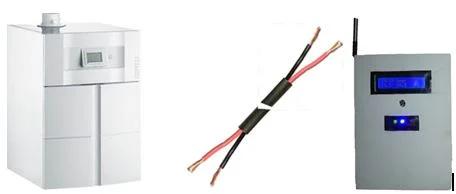
Parts used in the Connected Heating Thermostat:
- Arduino Nano 3.0 micro-controller
- ESP8266 DEV Olimex micro-controller
- DS1820 waterproof temperature sensor
- SONGLE SRD-05VDC double relay module
- I2C LCD 2x16 characters display
- I2C DS1307 Real Time Module with CR2032 battery
- AX-1838HS Infrared receiver
- FTDI interface
- IR remote controller
- LM1086 3.3v power regulator
- L7850CV 5v power regulator
- LEDs, resistors, capacitors, transistors, diodes, switches, connectors, wires, and PCB breadboards
What is the purpose?
- Increase the comfort by heating your house exactly as you want
- Make savings and reduce greenhouse gas emissions by heating your house only when you need
- Keep control on your heating wherever you are
- Be proud you did it yourself
Step 1: How Does It Increase Your Comfort ?

You will define 4 different temperature instructions that will be automatically selected based on your schedule.
You will express your need as a expected temperature at a time of the day and the system will start to heat at the optimal time to reach your expectation.
Back home earlier today, use your phone to anticipate the start of your heating
The system will deliver a very stable temperature that will fit precisely with your need.
Step 2: How Will You Make Savings and Reduce Greenhouse Gas Emissions ?

Knowing your schedule, the system will heat only when you need it.
The system will take the outisde temperature into account optimize heating.
Back home later today, use your phone to postpone the start of your heating.
You will able to tune the system to fit with your equipment.
Step 3: How Will You Control of Your Heating Wherever You Are ?
The system is WIFI connected.
You will use your laptop to set up, tune and update the schedule of your system.
Out of home, you will use your phone to anticipate or postpone the start of your heating
Step 4: Temperature Control
A PID controller is used for the heating regulation.
It is used to control the way to reach the expected temperature and keep it as close as possible to the target.
The PID parameters can be adjust to your environment (see tunning the system documentation).
Step 5: Instruction Controller
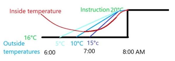
An instruction controller is designed to determine the heating starting time.
It takes into account inside, outside temperatures and the boiler capacity to determine dynamically the best time to start heating regarding your requirements.
This regulation can be tuned to your need with the “reactivity” parameter that you can modify.
Step 6: The Schedule
Temperature instructions are expressed as target (temperature, time). Meaning you want your house to be at that temperature at that definite time.
Temperature must be selected between the 4 references.
One instruction must be defined for each half hour of the schedule.
You can define one weekly based schedule and 2 daily ones.
Step 7: Architecture Overwiew
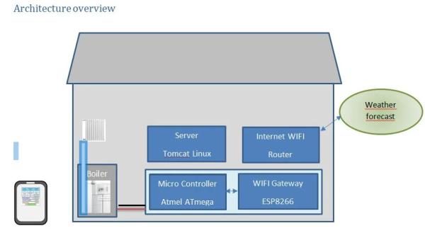
Take a look at the global architecture
It works with every boiler thru a normally open or normally closed contact.
Step 8: Micro-controllers Overview
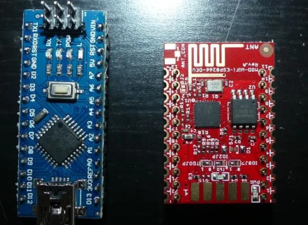
The core system runs on an Atmel ATmega micro-controller.
After code and parameters has been downloaded and clock synchronized, it can run 100% autonomously.
It communicates thru the serial link to take into account external information.
A ESP8266 micro-controller runs the gateway code for transforming serial link connection to a WIFI one.
Parameters are initially written in the eeprom and can be remotely modified and saved.
Step 9: Network Connection Overview
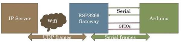
The network connection is made with a ESP8266 WIFI microcontroller. It is quite the same as the Gateway description “instructables” . Nevertheless the following changes have been made from this description: some useless GPIOs for this project are not used and the Arduino and ESP8266 are soldered on the same PCB.
Step 10: Server Overview
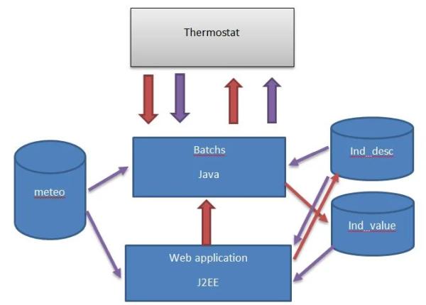
Java runs the server part of the system. HMIs use TOMCAT. MySQL is the database.
Step 11: Parts List
You will need these maincomponents
2 x micro-controllers
· 1 x Arduino – I chose a Nano 3.0 – you can find some at around 2.5$ (Aliexpress)
· 1 x ESP8266 – I chose -ESP8266-DEV Olimex – at 5.5€
1 x temperature sensor DS1820
· I chose a waterproof one – you can get 5 for 9€ (Amazon)
1 x double relay module (0 command)
· I chose SONGLE SRD-05VDC – you can find some at 1.5€ (Amazon)
1 x I2C LCD 2×16 characters
I already had one – you can find some for less than 4$ (Aliexpress)
1 x I2C DS1307 Real Time Module with CR2032 battery
· I already had one – you can find some for less than 4$ (Aliexpress)
you can find for a few euros
1 x Infrared receiver
· I chose AX-1838HS you can find 5 for 4€
1 x FTDI
1 x IR remote controller (you can buy a dedicated on or use your TV one)
2 x power regulators (3.3v & 5v)
· I chose I x LM1086 3.3v & 1 x L7850CV 5v
And some few stuff
5 x LED
9 x 1K resistors
1 x 2.2K resistor
1 x 4.7K resistor
1 x 100
microF ceramic capacitor
1 x 330 microF ceramic capacitor
2 x 1 microF tentalum capacitor
2 x NPN transistors
4 x Diodes
2 PCB breadboard
2 x 3 pins switches
Some connectors and wires
Of course you need soldering iron and tin.
Step 12: Build the Power Sources
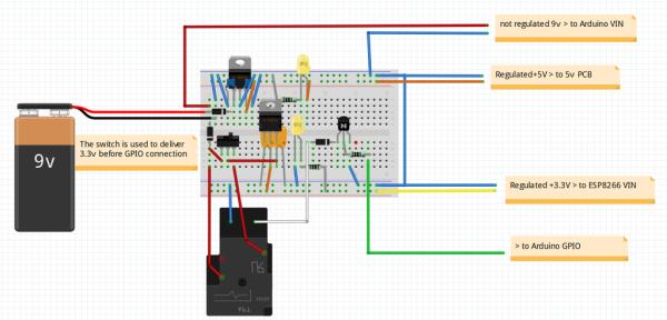
This fritzing file describes what to do.
It is better to start to build the power sources with a breadboard even if there are no difficulties.
Regulators can easily be replaced by other ones: just modify connections and capacitors according to your regulators characteristics.
Check it delivers a constant 5v and 3.3v even with a load (100 ohms resistors for instance).
You can now solder all the components on a breadboard PCB as below
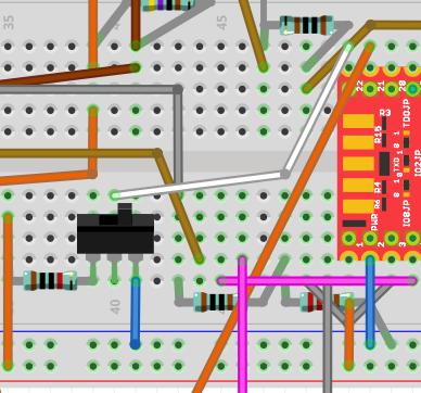
Step 13: Prepare the ESP8266
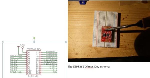
Plug your ESP8266 in a breadboard for an easiest soldering a below
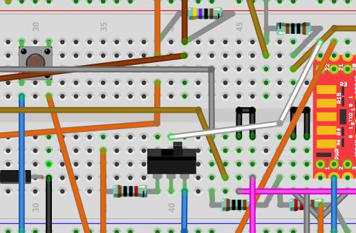
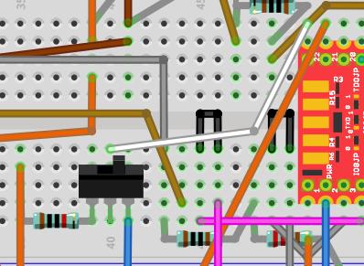
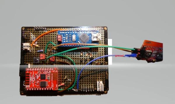
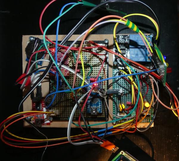
Step 14: Build the Electronics
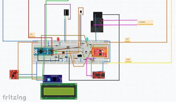
Reproduce the Fritzing reference.
I strongly suggest starting to build the electronics with a breadboard.
Put all parts together on the breadboard.
Connect carefully the power sources
Check power LEDs on the Arduino and ESP8266.
The LCD must light on.
Step 15: Let’s Do With the Gateway Configuration
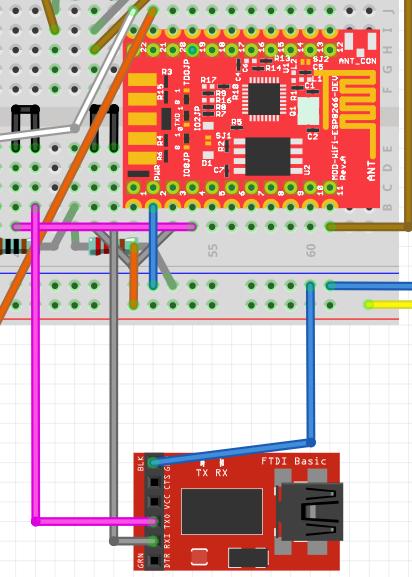
Connect the FTDI USB to your development station.
Set the serial link switch in order to connect ESP8266 to the FTDI as this
Step 16: Prepare to Download the Gateway Code
Start Arduino on your workstation.
You need ESP8266 to be known as board by the IDE.
Select the USB port and the appropriate board with Tools / boards menu.
If you do not see any ESP266 in the list that means you may have to install ESP8266 Arduino Addon (you can find here the procedure).
All the code you need is available on GitHub. It is time to download it !
The main code of the Gateway is there:
On top of standard Arduino and ESP8266 includes the main code need these 2 includes:
LookFoString that is used to manipulate strings and is there: https://github.com/cuillerj/LookForString
ManageParamEeprom that is used to read and store parameters in Eeprom ans is there: https://github.com/cuillerj/ManageParamEeprom
Once you get all the code it’s time to upload it into the ESP8266.
First connect the FTDI to an USB port of your computer.
I suggest you check the connection before trying to upload.
- · Set the Arduino serial monitor to the new USB port.
- · Set the speed to 115200 both cr nl (defaut speed for Olimex)
- · Power on the breadboard (ESP8266 comes with software that deals with AT commands)
- · Send “AT” with the serial tool.
- · You must get “OK” in return.
If not check your connection and look at your ESP8266 specifications.
If you got “OK” your are ready to upload the code
Step 17: Download the Gateway Code 1/2
- Power off the breadboard, wait a few seconds,
- Press on the push button of the breadboard and power on
- Release the push button It is normal to get some garbage on the serial monitor.
- Press on the upload IDE as for an Arduino.
- After the upload completed set serial speed to 38400.
Step 18: Download the Gateway Code 2/2
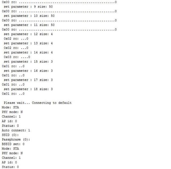
You would see something as in the picture.
Congratulation you successfully uploaded the code !
Step 19: Set Your Own Gateway Parameters
Keep opened the Serial Monitor (speed 38400) of the IDE
- Power off the breadboard, wait a few seconds
- Use the switch to set the configGPIO to 1 (3.3v)
- Scan the WIFI by entering the command:
- ScanWifi. You will see a list of the detected network.
- Then set your SSID by entering “SSID1=yournetwork
- Then set your password by enterind “PSW1=yourpassword
- Then enter “SSID=1” to define the current networ
- Enter “Restart” to connect the Gateway to your WIFI.
You can verify you got an IP by entering “ShowWifi”.
The blue LED will be on and the red LED blinking
It’s time to define your IP server address by entering the 4 subaddresses (server that will run the Java test code). For instance for IP=192.168.1.10 enter :
- “IP1=192”
- “IP2=168”
- “IP3=1”
- “IP4=10”
Define IP ports as:
- · routePort=1840 (or else according to your application configuration see “Server installation guide”)Enter “ShowEeprom” to check what you just stored in EepromNow set the GPIO2 to ground to leave the configuration mode (use the switch to do so)Your Gateway is ready to work !The blue LED must go on as soon as the gateway is connected to your WIFI.There are some others commands you could find in the gateway documentation.
- Set the ESP8266 IP address as permanent inside your DNS
Step 20: Prepare Arduino Connection
Firstly, unplug the serial link connectors to avoid USB conflict.
Step 21: Let’s Do Some Tests
Before working with the Thermostat code let’s do some tests with the IDE example sources
Connect the Arduino USB to your workstation.
Chose Serial Port, set speed to 9600 and set card type to Nano.
Check the temperature sensor
Open Files/ examples /Max31850Onewire / DS18x20_Temperature and modify OneWire ds(8); (8 instead of 10).
Upload and check it works. In case not check your DS1820 connections.
Check the clock
Open Files/ examples / DS1307RTC / setTime program
Upload the code and check you get the right time.
Check the LCD
Open Files/ examples / liquid cristal / HelloWorld program
Upload the code and check you get the message.
Check the remote control
Open Files/ examples / ArduinoIRremotemaster / IRrecvDemo program
Modify the PIN to 4 – upload the code
Use your remote controller and check you get the IRs code on the monitor.
It is time to choose the remote control 8 different keys you want to use as below:
- · increase temperature instruction
- · decrease temperature instruction
- · switch off the thermostat
- · select the week agenda mode
- · select the first day agenda mode
- · select the second day agenda mode
- · select the not freezing mode
- · power on/off the WIFI gateway
Since you made your choice use the key, copy and save in a text document the received codes. You will need this information later.
Step 22: Check the Network Connection
To check your work the best is to use the Arduino and Java examples.
Arduino
You can download it there: https://github.com/cuillerj/TestSerialLinkLibrary
It includes SerialNetwork library that is here: https://github.com/cuillerj/SerialNetwork
Just upload the code inside your Arduino.
Server
The server example is a Java program that you can download here: https://github.com/cuillerj/ESP8266SerialUdpGatew…
Just run it
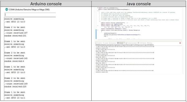
Look at the Java console.
Look at the Arduino monitor.
Arduino send 2 different packets.
· The first one contains the digital pins 2 to 6 status.
· The second one contains 2 random values, the voltage level of A0 in mV and incremental count.
The Java program
· print the received data in hexadecimal format
· reply to the first kind of data with a random on/off value to set on/off the Arduino LED
· reply to the second kind of data with the received count and a random value.
You must see something like above.
You are now ready to work on Thermostat code!
Step 23: Prepare the Arduino
Connect the Arduino USB to your workstation.
Set speed to 38400.
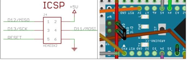
We need to set the Arduino in configuration mode
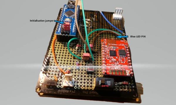
Plug a connector on the ICSP so that GPIO 11 is set to 1 (5v)
Step 24: Download Arduino Code
Thermostat sources are available on GitHub
First download this library and copy files in your usual library.
Then download these sources and copy files in your usual Arduino sources folder.
Open Thermosat.ico and compile and check you do not get errors
Download the Arduino code.
The Arduino will start automatically.
Wait for the message “end init eeprom”.
The default parameter’s values are now written in the eeprom.
Step 25: Restart the Arduino
The arduino has been initialized and must be set in running mode before being restarted.
Plug the connector on the ICSP so that GPIO 11 is set to 0 (ground) to set the Arduino in running mode.
Reset the Arduino.
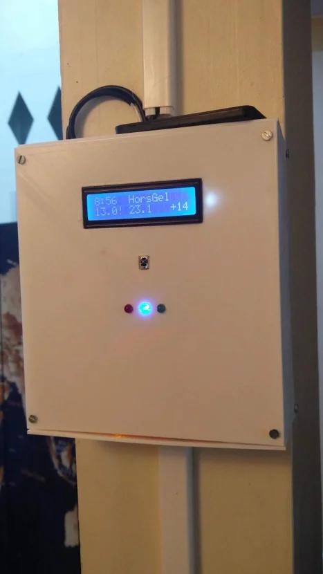
You must see time on the LCD and the yellow LED must be on. (You will see 0:0 if the clock has not be synchronized or time lost (powered of and no battery)).
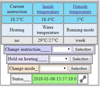
Step 26: Check LCD
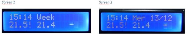
You will see alternatively 3 different screens.
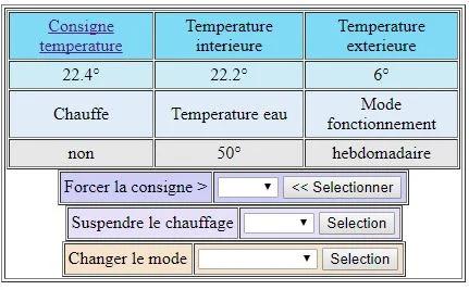
Common to screen 1 & 2:
- at the left of the top: the actual time
- at the left of the bottom: the actual temperature instruction
- at the middle of the bottom the: actual inside temperature (DS1820)
Screen 1:
- at the middle of the top: actual running mode
Screen 2:
- at the middle of the top: actual day of the week
- at the right of the top: day & month numbers
The 3rd one is described in the maintenance guide.
Step 27: Test Relays
Test the Gateway relay
At this stage you must be WIFI connected and the blue LED must light on.
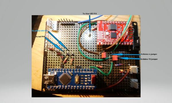
Press the remote controller key you selected to power on/off the WIFI gateway. The relay must switch off the ESP8266 and the blue LED.
Wait a few seconds and press again the remote controller key. The WIFI gateway must be powered on.
Within a minute le the gateway must be connected, and the blue LED must light on.
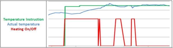
Test the boiler relay
First look at the red LED. If temperature instruction is much higher than the inside temperature the LED must light on. It takes a few minutes after the start for the Arduino to get enough data to decide whether or not to heat.
If the red LED is on, decrease the temperature instruction to set it low below the inside temperature. Within a few seconds the relay must switch off and the red LED light off.
If the red LED is off, increase the temperature instruction to set it low below the inside temperature. Within a few seconds the relay must switch on and the red LED light on.
If you do it more than one time, bear in mind that the system will not react immediately to avoid too fast switch the boiler.
That’s the end of the breadboard work.
Step 28: Solder the Power Supply 1/4
I suggest using 2 different PCB: one for the power supply and one for the micro-controllers.
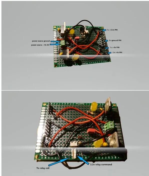
You will need connectors for;
· 2 for 9v input power supply
· 1 for +9v output
· 1 for +3.3v output (I did 2)
· 2 for +5v output (I did 3)
· 2 for relay command
· 2 for relay power
Step 29: Solder the Power Supply 2/4
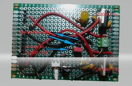
Here is the Frizting scheme to follow !
You can see above the parts numbers according to the Fritzing model.
Step 30: Solder the Power Supply 3/4
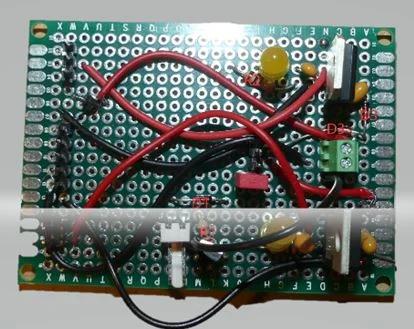
You can see above the parts numbers according to the Fritzing model.
Step 31: Solder the Power Supply 4/4
You can see above the parts numbers according to the Fritzing model.
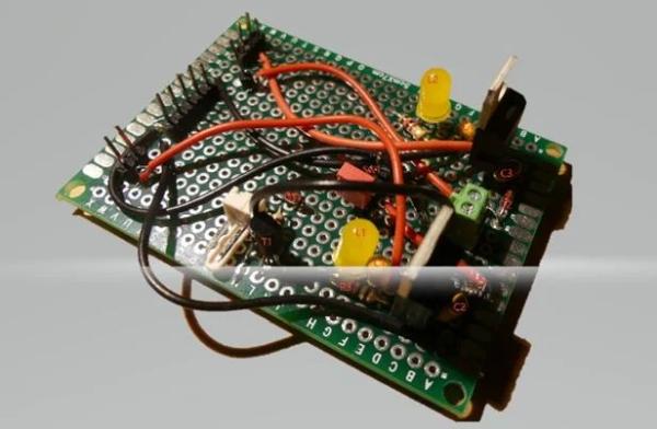
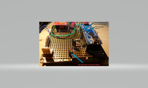
Step 32: Solder the Micro-controllers on PCB 1/7
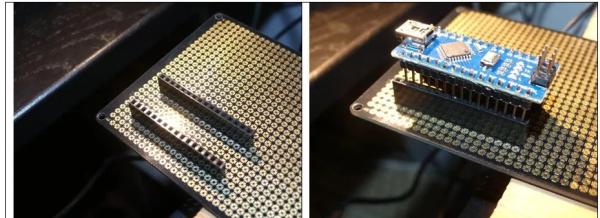
I suggest not soldering the Arduino and ESP8266 directly on the PCB
Instead use connectors as below in order to be able to replace easily the microcontrollers
Step 33: Solder the Micro-controllers on PCB 2/7
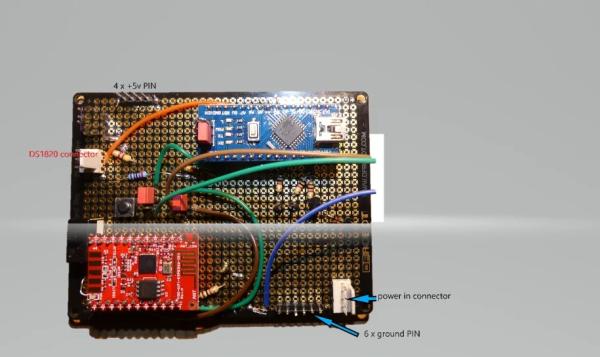
You will need connectors for:
- 3 x +5v (I did one spare)
- 6 x ground
- 3 x for DS1820
- 3 x for LED
- 1 x IR receiver
- 2 x for relay command
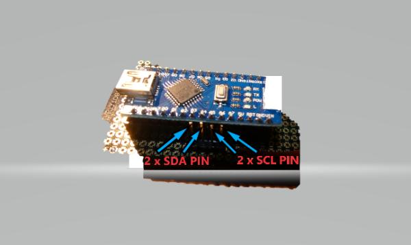
- 4 x for I2C bus
Here is the Frizting scheme to follow !
You can see above the parts numbers according to the Fritzing model.
Step 34: Solder the Micro-controllers on PCB 3/7
You can see above the parts numbers according to the Fritzing model.
Step 35: Solder the Micro-controllers on PCB 4/7
You can see above the parts numbers according to the Fritzing model.
Step 36: Solder the Micro-controllers on PCB 5/7
You can see above the parts numbers according to the Fritzing model.
Step 37: Solder the Micro-controllers on PCB 6/7
You can see above the parts numbers according to the Fritzing model.
Step 38: Solder the Micro-controllers on PCB 7/7
You can see above the parts numbers according to the Fritzing model.
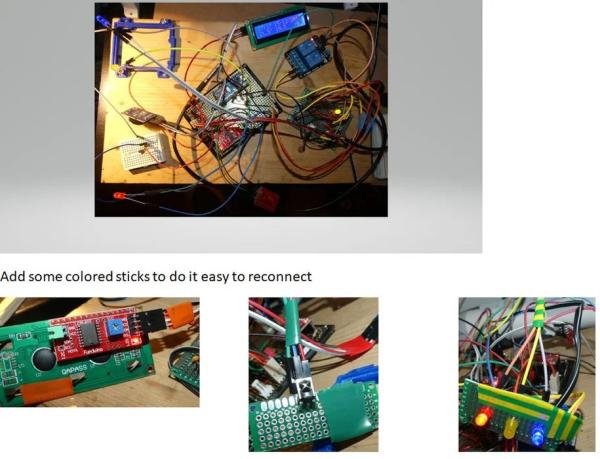
Step 39: Connect and Check Altogether Before Putting in the Box
Step 40: Screw PCBs on a Piece of Wood
Step 41: Let’s Do the Wooden Cover Box
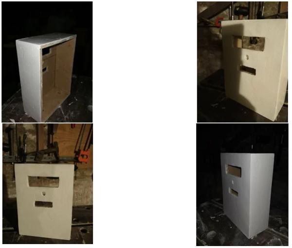
Step 42: Put All in the Box
Step 43: Create Server Code Project
Start your IDE environment
Download the batches sources from GitHub
Download the J2EE sources from GitHub
Start your Java IDE (Eclipse for instance)
Create Java project “ThermostatRuntime”
Import the downloaded batches sources
Create a J2EE project (Dynamic Web Project for Eclipse) “ThermostatPackage”
Import the downloaded J2EE sources
Step 44: Define Your SQL Connection
Create a “GelSqlConnection” class in both Java and J2EE project
Copy and past the GetSqlConnectionExample.java content.
Set your MySql server user, password and host you will use to store data.
Save GelSqlConnection.java
Copy and past GelSqlConnection.java int the ThermostatRuntime project
Step 45: Create the Database Tables
Create the following tables
Use Sql script to create indDesc table
Use Sql script to create indValue table
Use Sql script to create stations table
Initialize tables
Download loadStations.csv file
open the csv file
modify st_IP to fit with your network configuration.
- the first address is the Thermostat one
- the second Thermostat is the server one
save and load the stations table with this csv
load the ind_desc table with this csv
Step 46: Define Access Control

You can do whatever control you want by modifying “ValidUser.java” code to fit your security need.
I simply check for IP address to authorize modification. To do the same just create the Security table and insert a record in this table as above.
Step 47: Optional
Outside temperature
I use this weather forecast API to get information for my location and it works pretty well. A shell with curl hourly extracts temperature and store in database. You can adapt the way you will get the outside temperature by modifying the “KeepUpToDateMeteo.java” code.
Home security
I interfaced my home security system with the Thermostat in order to decrease automatically the temperature instruction when I leave home. You can do something similar with the “securityOn” field in the database.
Boiler water temperature
I already monitor the boiler water in and out temperature with an Arduino and 2 sensors DS1820 so I added information to the WEB HMI.
Step 48: Start the Runtime Code
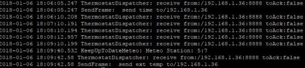
Export the ThermostatRuntime project as a jar file
Unless you want to modify UDP ports start batches with the command:
- java -cp $CLASSPATH ThermostatDispatcher 1840 1841
CLASSPATH must contain access to your jar file and mysql connector.
You must see something like above in the log.
Add an entry in the crontable to start at reboot
Step 49: Start J2EE Application
Export the ThermostatPackage as a WAR.
Deploy the WAR with the Tomcat manager
Test the application youserver:port/Thermostat/ShowThermostat?station=1
You must see something like above
Step 50: Synchronize the Thermostat and Server
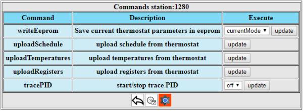
Use the command menu of the HMI to do the following steps
· Upload temperatures
· Upload registers
· Upload schedule
· Write eeprom / select All
Step 51: Connect the Thermostat to the Boiler
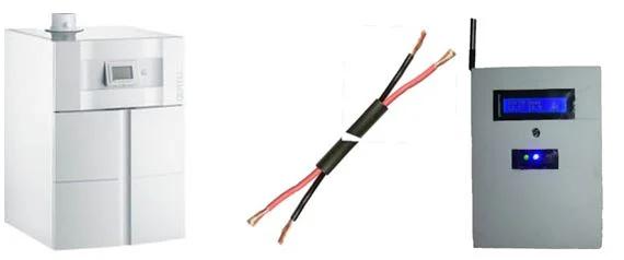
Before doing read carefully the boiler instructions. Take care to high voltage.
The thermostat must be connected to a simple contact with a 2 wires cable.
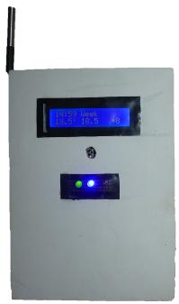
Step 52: Enjoy Your Heating Control System
You are ready to configure the system to precisely fit your need !
Set your reference temperatures, your schedules.
Use the Thermostat documention to do so.
Start the PID trace. Let the system run a few days and then use collected data to tune the Thermostat
Documentation provides specifications you can refere to if you want to do changes.
If you need more information post me a request. I will be pleased to answer.
This takes part of a home automation infrastructure
Step 53: 3D Printing Box
I got a 3D printer and printed this box.
Source: Make Your Own Connected Heating Thermostat and Make Savings With Heating
- How does the system increase user comfort?
The system defines four temperature instructions automatically selected by schedule to deliver a stable temperature that fits precise needs. - Can the system help make savings and reduce emissions?
Yes, it heats only when needed by taking outside temperature into account and optimizing the start time dynamically. - Does the project use Wi-Fi for remote control?
Yes, an ESP8266 micro-controller provides Wi-Fi connectivity allowing users to anticipate or postpone heating from their phone. - What type of controller is used for temperature regulation?
A PID controller is used to control how the expected temperature is reached and kept as close as possible to the target. - What components form the core of the system?
The core runs on an Atmel ATmega micro-controller which communicates via serial link to an ESP8266 gateway. - How are temperature instructions defined in the schedule?
Instructions are expressed as target temperature and time, requiring one definition for each half hour of the weekly or daily schedule. - What software runs the server part of the system?
Java runs the server part while HMIs use TOMCAT and MySQL serves as the database. - Can the reactivity parameter be tuned?
Yes, the regulation can be tuned to specific needs by modifying the reactivity parameter in the instruction controller.