Summary of Make a digital “meow” from analog clock using arduino
This tutorial demonstrates modifying a Kit Cat Clock to play a "meow" sound hourly using an Arduino Uno and an Atmega 328P-PU. The project leverages the clock's internal magnet motor, detecting its magnetic field with a Hall effect sensor to generate digital pulses. These pulses are counted by the microcontroller, which triggers audio playback via a small speaker after reaching a specific interval.
Parts used in the Kit Cat Clock Meow Project:
- Arduino Uno R3
- Breadboard
- Jumper Wires
- Resistors (350 Ohm, 150 Ohm, 220 Ohm, 280 Ohm, 10K Ohm, 330 Ohm)
- Capacitors (100 uF, 10 uF, 22 pF)
- 16 Mhz Crystal Oscillator
- 0.5 Watt small speaker
- 7.5 Volt AC wall adapter
- 7805 Voltage regulator
- Soldering Iron and Solder
- Protoboard
- Super glue
- Heat shrink
- Hot Glue gun
- Takane Quartz Clock
- Hall effect sensor (SS41 family)
Is your analog clock just not doing enough stuff? Want to do digital things with an analog clock?
This tutorial will show you how to make a Kit Cat Clock play a “meow” sound clip, at precise time intervals, using the Atmega 328P-PU via the Arduino Uno development board. In my example, the meow will occur hourly. This doesn’t have to be a Kit-Cat clock either, this idea may work with other clocks that use a magnet motor.
Assumptions (skip if you’re already an expert in everything)
The project encompasses many intermediate to advanced skills such as burning a bootloader and soldering of wires. Therefore, some requisite knowledge and skills are needed before proceeding. I will assume that you know how, or will at least be prepared to do the following:
Burning a bootloader onto the Atmel328P-PU (unless yours already has one).
Uploading “sketches” onto the Atmel328P-PU via Arduino
Entering commands into a terminal emulator or command prompt (windows)
Using a soldering iron to make connections between components.
Possible usage of a drill or Dremel tool for trimming/cutting plastic parts, and boring holes.
Materials
Arduino Uno R3 x 1
Breadboard x 1
Jumper Wire (enough pieces)
Resistors:
350 Ohm x 1
150 Ohm x 1
220 Ohm x 1
280 Ohm x 1
10K Ohm x 1
330 Ohm x 1 (optional if you want the LED while using Arduino on Breadboard Setup)
Capacitors:
100 uF x 1
10 uF x 1
22 pF x 2 (may be optional)
16 Mhz Crystal Oscillator
0.5 Watt small speaker (approximately 50.8 mm diameter) x 1
7.5 Volt AC wall adapter (I used the Vtech brand found at Toys R Us) x 1
7805 Voltage regulator x 1
Soldering Iron and Solder
Protoboard (or some other final project board that will be small enough to fit with the clock case)
Super glue
Heat shrink (optional)
Hot Glue gun (optional)
Takane Quartz Clock (assuming you need to replace the default one inside Kit Cat, as I did)
Hall effect sensor x 1
I used the SS41 family of Hall effect sensors. These sensors are sensitive enough to detect the relatively weak magnetic field from the clock magnet motor. The specific one that I purchased may be found here
Step 1: General Project Overview:
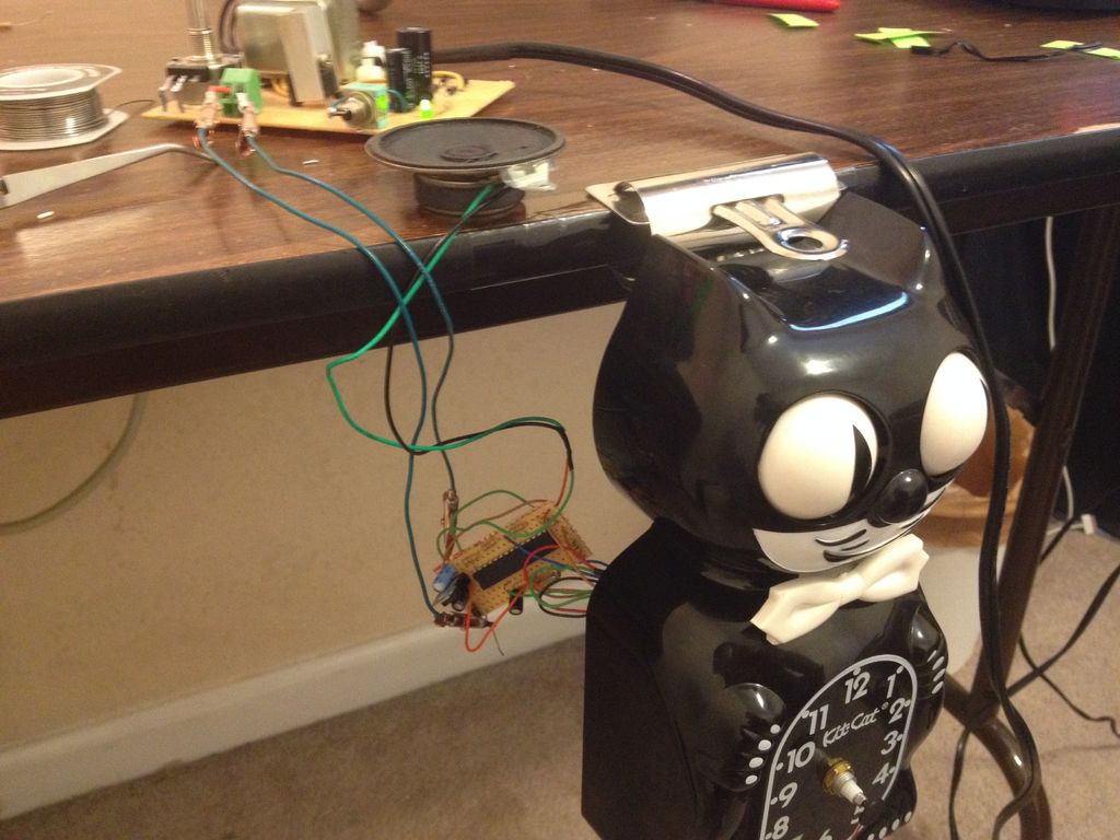
An interesting aspect of this project is using analog devices (in this case an analog clock) to interact with the digital world of the Atmel 328P-PU. Arduino is probably one of the simplest ways to achieve this. I will be using the typical clock motor found inside the classic Kit Cat clocks to generate a digital pulse which will feed into the Atmel chip. The reason this will work is because the clock motor utilizes a permanent magnet, located within the proximity of a coil, to create the mechanical torque necessary to spin the clock hands. I will take advantage of this magnetic field by using a Hall Effect sensor to detect the magnetic flux from the clock motor. The sensor will output a digital HIGH whenever one of the poles from the magnet is facing the sensor, and then output a LOW when the opposite pole is near the sensor. This pole transition occurs every second, or has a frequency of 1 Hz and is the reason why this serves as an ideal motor for driving clock hands.
Note: the sensor isn’t actually touching the magnet, it’s just very close to it. The pictures show how close I was required to place the sensor, in order to get readings.
The pictures here show the inside of the actual clock and the magnet motor to the right side. The type of clock is called a “Takane Quartz” and they are pretty common in cheap analog clocks.
Once we have a steady pulse coming from the sensor, all sorts of things can be done digitally, and really it’s only limited to your imagination on what you can do. In this tutorial I will simply make a counter that counts the clock pulses (from the Hall sensor), and upon finishing the count, then plays a “meow” audio clip.
The first step involves mounting the Hall sensor near enough to the magnet motor so that you can get a good reading. I had to place the sensor very close to my magnet motor to get an output. You can test the sensor by attaching something like an LED to the output pin of the sensor and then turn the clock on. If this works then the LED should blink every other second. This is because the output is only HIGH while one of the poles is facing the sensor (let’s say the north pole as an example); when the opposite pole (south) is facing the sensor the output is LOW.
After you have determined an appropriate location and distance to get your readings, you should then begin thinking about how to mount it there permanently. I chose to use super glue to hold the sensor in place. I also considered the location because of where the back casing would be. I had to cut out a small rectangular hole so the sensor pins would be accessible. You should determine what works best because although these clocks are nearly the same, sometimes the layout is slightly different inside, and the placement of the sensor may vary depending on the particular clock that you have.
Step 2: Soldering wire to the input pins of sensor
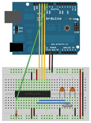
Now it’s time to solder the pins to wire. The reason I did this was for two reasons: First you want to be able to test the sensor as you continue working, and also because you will need those wires when you connect them onto your breadboard and finally the protoboard. Note, using different colored wire may make it easier when you need to quickly identify the pins. That’s what I did.
Pinout configuration may be found at this site
Step 3: Preparing the audio file
If you already know how to convert a .WAV file to a C file, then you can skip or skim through this step.
Now that the sensor is attached to the appropriate pins on the breadboard, you will need to upload the audio sketch onto the Atmel328P. But first, some modifications and “massaging” needs to be done first. This is where you could make some of your own modifications and I will go into some (but not all) of the detail regarding the use of Audacity and wav2c programs. You should go ahead and open the code that I’ve provided in your Arduino IDE. When you open the sketch in the Arduino IDE, the first tab is a slight alteration of the PCM audio sketch written by Michael Smith, the original may be found on the Arduino site:
http://playground.arduino.cc/Code/PCMAudio
Audacity is an audio editing program. It’s very powerful and allows a .wav file to be exported as an 8-bit mono, unsigned .wav file. This is necessary to get the file size reduced and also to maximize the compatibility with the audio playback sketch. You may be able to work around different bit rates and sizes, but I haven’t experimented with it. We will only be using the necessary features in Audacity to get the job done.
Wav2c, as the name implies, can convert a .wav file to a C file. This is also necessary because the .wav file by itself is too large to fit in the memory of the 328P-PU. As of this writing you can download the source code directly from github. You may also be able to get compiled versions from other websites. Either way, you should use it or another similar program for the conversion process.
 HallCounter_final.ino
- How can I make an analog clock play a digital sound?
You can use an Atmega 328P-PU via an Arduino Uno to detect the clock's magnet motor pulses with a Hall effect sensor and trigger an audio clip. - What components are required to detect the clock's movement?
A Hall effect sensor, specifically the SS41 family, is used to detect the magnetic flux from the clock motor without touching it. - Can this project be done without soldering skills?
No, the project assumes knowledge of burning a bootloader, uploading sketches, using a terminal emulator, and soldering wires between components. - How do I prepare the audio file for the microcontroller?
You must convert a .WAV file to an 8-bit mono, unsigned format using Audacity and then convert that file to a C file using wav2c to fit the memory. - Does the Hall effect sensor need to touch the magnet?
No, the sensor does not touch the magnet; it only needs to be placed very close to it to detect the magnetic field poles. - What frequency does the clock motor output?
The pole transition occurs every second, resulting in a frequency of 1 Hz which serves as the ideal motor drive signal. - Is it necessary to replace the original clock mechanism?
You may need to replace the default clock inside the Kit Cat with a Takane Quartz Clock if the original layout prevents proper sensor placement. - How can I verify the sensor is working before final assembly?
You can attach an LED to the sensor output pin; if working correctly, the LED should blink every other second when the clock is on.