Summary of Diy Xbox wireless controller adapter for Pc
This guide shows how to connect an Xbox 360 RF module from a RROD console to a PC using an Arduino: solder USB and signal wires (with two diodes for 3.3V), program the Arduino with provided code to drive LEDs and send a sync command, and modify/install the Microsoft Xbox 360 Accessories driver INF so Windows recognizes the RF module. Once installed, press the repurposed power button to sync controllers and use them with PC games.
Parts used in the Diy Xbox wireless controller adapter for Pc:
- Arduino UNO
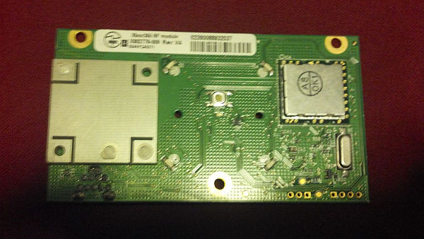
- Xbox 360 RF Module (from a broken Xbox)
- Soldering iron
- Solder
- USB cable
- 2 x 1N4001 diodes
- Wire cutters
- Wire strippers
- Pliers
- Wires (22 AWG and/or 30 AWG Kynar)
This instructable will go over the steps to connect a RF module from an RROD xbox to your computer so you can use a wireless controller with your computer. ******DISCLAIMER******* DONT TRY THIS IF YOU DONT HAVE ANY EXPERIENCE WITH ELECTRONICS/SOLDERING OR COMPUTERS IM NOT RESPONSIBLE IF YOU SCREW UP…. now that we’ve gotten that out of the way
Step 1: Soldering ….
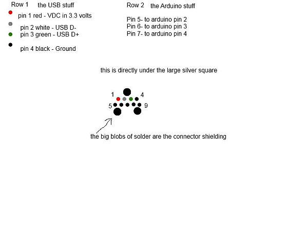
First strip the usb cable, inside there will be a black wire, a red wire, a white wire, and a green wire. there will also be some shielding and a shield ground wire (usually not covered) these you can cut back to the plactic. strip about an 1/8th inch of plastic off each of the four wires.
Next you will need to solder the diodes to gether in series ->-> and then solder the side with the line on it to pin 1 and the side without the line to the red wire in the usb cable **** make sure the diodes are the right way around before soldering****
Now you can solder the white wire to pin 2, the green wire to pin 3, and the black wire to pin 4
solder a piece of wire to each of pins 5-7 too, make sure they are long enough to connect to your arduin.
Step 2: Code
Original work by (yaywoop) / additional ideas from Alexander Martinez – modified by dilandou (www.dilandou.com, www.diru.org/wordpress)
First sends LED initialisation code followed by LED startup animation code, then sleeps until a button press for sync command.
RF module must be powered with 3.3V, two diodes in series with USB 5v will do. Connect the USB wires to a host computer, and the data and serial wires to Arduino.
of course, make sure to have a common ground */
#include <avr/sleep.h>
#define sync_pin 2 //power button repurposed for sync button (pin 5 on the module)
#define data_pin 3 //data line (pin 6 on the module)
#define clock_pin 4 //clock line (pin 7 on module)
int led_cmd[10] = {0,0,1,0,0,0,0,1,0,0}; //Activates/initialises the LEDs, leaving the center LED lit.
int anim_cmd[10] = {0,0,1,0,0,0,0,1,0,1}; //Makes the startup animation on the ring of light.
int sync_cmd[10] = {0,0,0,0,0,0,0,1,0,0}; //Initiates the sync process.
volatile boolean sync_enable = 0;
void sendData(int cmd_do[]) {
pinMode(data_pin, OUTPUT);
digitalWrite(data_pin, LOW); //start sending data.
int prev = 1;
for(int i = 0; i < 10; i++){
while (prev == digitalRead(clock_pin)){} //detects change in clock
prev = digitalRead(clock_pin);
// should be after downward edge of clock, so send bit of data now
digitalWrite(data_pin, cmd_do[i]);
while (prev == digitalRead(clock_pin)){} //detects upward edge of clock
prev = digitalRead(clock_pin);
}
digitalWrite(data_pin, HIGH);
pinMode(data_pin, INPUT);
}
void initLEDs(){
sendData(led_cmd);
delay(50);
sendData(anim_cmd);
delay(50);
}
void wakeUp(){
sync_enable = 1;
}
void sleepNow() {
set_sleep_mode(SLEEP_MODE_PWR_DOWN); // set sleep mode
sleep_enable(); //enable sleep bit
attachInterrupt(0, wakeUp, LOW);
sleep_mode();
sleep_disable(); //disable sleep bit
detachInterrupt(0); // disables interrupt 0 on pin 2
}
void setup() {
Serial.begin(9600);
pinMode(sync_pin, INPUT);
digitalWrite(sync_pin,HIGH);
pinMode(data_pin, INPUT);
pinMode(clock_pin, INPUT);
delay(2000);
initLEDs();
// sendData(sync_cmd);
}
void loop(){
Serial.println(“Sleeping.”);
sleepNow();
delay(200);
if(sync_enable==1) {
Serial.println(“Syncing.”);
sendData(sync_cmd);
sync_enable = 0;
}
}
or you can get it from here http://diru.org/wordpress/hacking/xbox-360-rf-module-arduino/
you will need to program your arduino with this code
I did not come up with this code all credit for this code goes to dilandou and Alex Martinez
Step 3: Software
download this http://www.microsoft.com/hardware/en-us/d/xbox-360-wireless-controller-for-windows
and install
go to the install folder (Microsoft Xbox 360 Acessories) in your program files
find Xusb21.inf this is the driver file for the software you will be modifying it so it will recognise your hardware
open it with a text editor or a program like Notepad++ (recomended)
find these headers [MSFT.NTx86.6.0], [MSFT.NTamd64.6.0], [MSFT.NTx86], and [MSFT.NTamd64].
you are going to replace the 5 lines of code under each of them
the original code looks like this
%XUSB21.DeviceName.Wired%=CC_Install, USB\Vid_045E&Pid_028E
%XUSB21.DeviceName%=CC_Install, USB\Vid_045E&Pid_0719
%XUSB21.DeviceName.Wired%=CC_Install, USB\MS_COMP_XUSB10
%XUSB21.DeviceName%=CC_Install, USB\MS_COMP_XUSB20
%XUSB21.DeviceName.Jump%=CC_Install, USB\Vid_045E&Pid_028F
what you will put in its place looks like this
%XUSB21.DeviceName.Wired%=CC_Install, USB\Vid_045E&Pid_0291
%XUSB21.DeviceName%=CC_Install, USB\Vid_045E&Pid_0291
%XUSB21.DeviceName.Wired%=CC_Install, USB\UNKNOWN
%XUSB21.DeviceName%=CC_Install, USB\UNKNOWN
now save it (make sure you save as a .inf file or it wont work)
now hook up the three extra wires on the RF module to the arduino if you havent already and plug the usb cable into your computer it should light up but controllers wont sync yet
change the Microsoft Xbox 360 Acessories folder so that it is no longer read only
now open the device manager and find the unidentified usb device (the one with the yellow triangle)
right click and select update drivers then in the update driver software window select browse my computer then let me pick from a list of drivers for my device then select show all then have disk
finally navigate to the modified Xusb21.inf file and select it and install
after you install the drivers the controller should sync with the RF Module just hit the power button which has been repurposed as a sync button and sync like you would to an xbox
it should now work with any game that allows you to use a gamepa.
Arduino UNO – a wonderfull microcontroller board you can get it on ebay or at radioshack
RF Module – from a broken xbox/ ebay
Soldering Iron – mine is a cheap radio shack model
Solder – also avalible at a local radio shack
USB cable – scavenged from old electronics (i found it in my parts bin)
2 1N4001 diodes
Wire cutters – for cutting wire….
Wire strippers – for stripping wire…
pliers – for holding small things/ bending wire…
Wire – i have bolth some 22 AWG wire from radioshack and some fancy 30 AWG Kynar wire (easily avalible on ebay) pretty much any wire will work as long as it is small enough to solder to the connectons on the RF shield
For more detail: Diy Xbox wireless controller adapter for Pc
- How do you power the RF module from USB?
Use two diodes in series on the USB 5V red wire to drop voltage to about 3.3V as required by the RF module. - Can the Arduino control the RF module LEDs and sync?
Yes, the provided Arduino code initializes LEDs, runs the startup animation, sleeps, and sends the sync command when the repurposed power pin is pressed. - What USB wires connect to which RF module pins?
Red (5V via diodes) to pin 1, white to pin 2, green to pin 3, black to pin 4; pins 5-7 get wires to the Arduino. - How do you get Windows to recognize the RF module?
Modify the Xusb21.inf driver file from the Microsoft Xbox 360 Accessories installer per instructions, then update the unidentified USB device in Device Manager using the modified INF. - Do you need to change file attributes before installing the modified driver?
Yes, change the Microsoft Xbox 360 Accessories folder so it is no longer read only before installing the modified INF driver. - Which Arduino pins are used in the example code?
sync_pin is digital pin 2, data_pin is digital pin 3, and clock_pin is digital pin 4. - What must you do before attempting this project?
Have experience with electronics, soldering, and computers; the author warns not to attempt if inexperienced. - Will the controller sync after driver installation?
Yes, after installing the modified drivers, press the repurposed power/sync button to sync the controller with the RF module.