This is the documentation page for the Spring 2012 DIY Telepresence project. Here you will find schematics, software, and guides for the robot. The goal of the project was to design a low-cost, easy to build telepresence robot. Some of the features include:
Segway based mobility plane
Robot arm
Aluminum frame
Two way-video conferencing using the WebRTC protocol
Wifi enabled remote control of the robot
HTML5 dynamically configurable web UI
Robot Operating System (ROS) control with Arduino interface
This project was undertaken between Fall 2011 to Spring 2012, and was developed by five team members: Daniel Kuo, Tri Nguyen, Dec Rachatasumrit, Michael Zhang, and William Zhong
Contents
1 Final Design Report
2 Guides
2.1 Hardware
2.2 Software
3 Robot Electronics and Power System
3.1 Electrical Schematic Diagram
3.2 How to Power on the Electronics
4 Frame Construction
4.1 Height Adjustment
5 Robot Arm
Final Design Report
DIY Telepresence Robot Report
Guides
Hardware
DIY Robot Electronics and Power System
DIY Electrical Schematic Diagram
DIY How to Power on the Electronics
DIY Height Adjustment
DIY Robot Arm
and so on…
Software
DIY Telepresence Software Architecture
DIY Telepresence HTML5 Design
Robot Electronics and Power System
Most of the electronics on the robot are powered off of the 12V lead-acid marine battery. Exceptions include the Segway and laptop, both of which contain seperate lithium-ion batteries. The electronics are controlled through a “Main Power Control” panel which distributes power to the robot subsystems:
Inverter: Generates 120VAC power from the 12VDC battery. The 120VAC rail is used to power the monitor and laptop.
Subsystem Power: Supplies power to a Mini-ATX PSU. This then provides a 5V rail for the webcam and flashlight/laser assemblies. Subsystem power is further distributed by the “Subsystem Power Control” panel on the robot shoulder.
Robot Arm PSU1: Powers an Mini-ATX PSU which supplies 12V power to the worm-drive motor controller, and 5V power to the two elbow servos and shoulder servo.
Robot Arm PSU2: Powers an Mini-ATX PSU which supplies 5V power to the two wrist servos and gripper.
Note: The “Panel Lighting” switch on turns on/off the LEDs on the control panel, but otherwise does not affect circuit operation. Turning off the LEDs can extend the battery life. Note:The “Main Power” switch is a 25A circuit breaker, that will shut off in the event of a short circuit.
Electrical Schematic Diagram
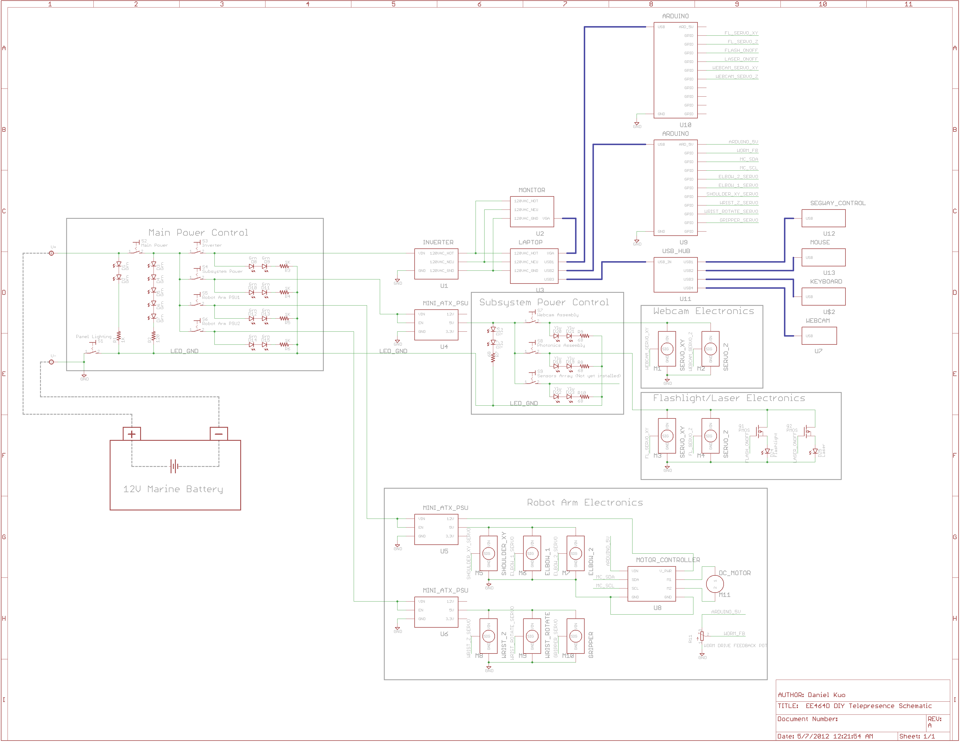
The schematic diagram presents a high-level overview of the electrical interconnects for the robot. Green lines represent wires, while blue signifies a USB or VGA cable. The electronics are organized into four main systems: Inverter, Subsystem Power, Robot Arm PSU1, and Robot Arm PSU2. 12V power is distributed to each system through the main power control, which supplies power through a marine battery. The Inverter outputs 120VAC, and powers the monitor and laptop. The Subsystem Power supplies energy to an ATX PSU, which is then used to power servos for the camera and flashlight/laser assemblies. Robot Arm PSU1 and PSU2 supply power to the upper and lower arm servos respectively using individual ATX PSUs.
DIY Telepresence Schematic Thumb.png
The schematic was created using Eagle CAD software. The source files are available below.
Schematic and library file download
Note: The library file contains only symbols for the devices. No PCB footprints are provided.
How to Power on the Electronics
If mobility is required, the Segway base can be turned on by pushing the power button on the back. Due to the battery placement, it may be necessary to use tool to push the button (such as a screwdriver).
The “Main Power Control” can be used to selectively power on the robots various subsystems. The power on sequence is listed below:
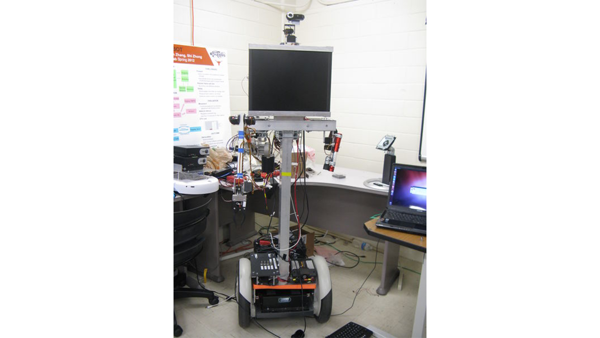
The main power control panel located at the base of the robot
Turn on the “Panel Lighting” switch. The “Main Batt.” LEDs should illuminate.
Flip the “Main Power” switch all the way towards the right. The “Main Power” LEDs will turn on.
Apply power to the selected subsystems as needed by flipping the toggle switches for either “Inverter”, “Subsystem Power”, “Robot PSU 1”, or “Robot PSU 2”. The respective LEDs will turn on when power is applied.
Note: The power button on the Inverter also needs to be pressed to enable 120V AC power.
Note: The Subsystem Power, Robot PSU1, and Robot PSU2 are all connected to Mini-ATX PSUs. These will not power on until a 5 second delay has elapsed.
The Subsystem Power Control is located on the robot shoulder. This is used to distribute 5V power to the webcam and flashlight/laser assemblies.
The monitor can be easily be turned on by pulling the lower right corner of the monitor forward. Such that the on button is depressed by pressure against the aluminum U-channel.
For more detail: DIY Telepresence Documentation