Every curious how DVDs work? Interested in learning some simple analog electronics? This Instructables will show you how to make an optical disk display project in only a few hours. What is an optical disk? An optical disk stores data/information and can be read or displayed using light.
You will learn about basic analog electronics, basic electronic optics, and various basic electrical components. You will be making a fun encoder, turning a digital light interface into an analog signal that controls a 7-seg display.
Step 1: 7 Segment Displays
A 7 segment display is an array of LEDs. 8 LEDs are used to create a pattern that looks like an ‘8’. Depending on which part of the 7-seg you light up, it can display any number from 0 to 9 and some letters (let L, A, S, H and more). Like RGB LEDs there can be common cathode and common anode 7-seg displays. We will use common cathode displays, which use two GND connections and 8 other connections to light up the individual sections of the display.
Step 2: Phototransistors
Phototransistors are light activated transistors. For this application, think of a transistor as a switch. When a voltage is applied to the base of the transistor, current flows from the collector to the emitter (we are using a npn transistor). In a phototransistor, we use light to trigger the base pin. So when light is shining on the sensor, current is allowed to flow. We will be using this as a switch for the 7-seg display. If there is light reaching the phototransistor, current will flow through the device and to the corresponding part of the 7-seg display.
There are two pins on the phototransistor, one is the collector and one is the emitter. The third pin is light!
Step 3: Motors
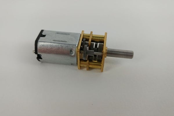
Motors are electromechanical devices used to move stuff. They are everywhere, from an animated holiday cards, to electric cars. We will be using a geared motor to turn our disk. The gears are necessary to slow down the speed of the motor. Geared motors come in a variety of speeds. Many start with a 12V motor and use gears to either speed up or slow down the rate of rotation. If you slow down the rotation, you will have more torque but less speed. If you speed up the rotation, you will have less torque but more speed. Things to keep in mind when you are designing your project!
Step 4: Optical Storage
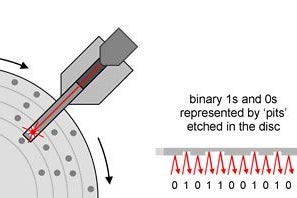
Our machine closely resembles an optical storage device, like a Blueray disk or a DVD. An optical storage device works by bouncing a laser off of a surface and back to a sensor. If there is a ‘pit’ (a small burn hole in the material) the laser takes longer to bounce back to the sensor. Each pit that the laser senses is considered a 1. Every other value is a 0. Combine enough of these binary 1s and 0s and you have data, aka information. So to summarize, optical storage is a bunch of burnt pits in a disk. The pattern of these pits determines the information stored.
Step 5: Design
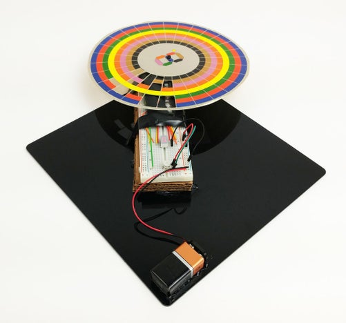
So how does all of this relate to our device? We will use cutouts instead of pits to allow light to pass through to sensors beneath the disk. The disk will be like a pizza with 28 slices, each having 8 cutouts. The cutouts in each slice will light up an individual section of the 7-seg. The disk is rotated using a motor so that each slice gets a turn controlling the 7-seg. 8 phototransistor sensors below the disk will sense the light being either blocked or allowed through. If there is a cutout and light is shining through, then current will be allowed to flow through the transistor and will illuminate the section of the 7-seg.
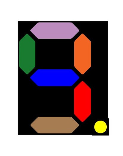
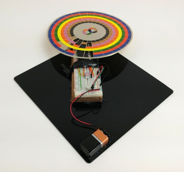
The second picture shows the disk with each color corresponding to a part of the 7-seg. If you cutout every color in one slice then the entire 7-seg will light up for the duration of that slice. If you cutout the purple part of the slice then the top element in the 7-seg will be illuminated. Cutout red and blue and the middle and bottom right section of the 7-seg will light up.
The simulation below shows the phototransistor array. Click one of the phototransistors and slide the dial. It simulates what happens when there is a cutout in the disk. When you slide the dial to the right you will notice the corresponding part of the 7-seg light up. The simulation also shows a motor with the speed controlled by a potentiometer. This is what controls the rate of rotation of the disk, which in turn controls how fast your message scrolls on the 7-seg.
Read more: Make an Optical Disk Display