This Instructable shows you how to add a high-resolution touch screen to your Arduino and make a synthesizer that controls colored LEDs! The techniques you learn here can serve as a foundation for other touch screen projects!
In this Instructable, you will learn:
- Where to get a high resolution 800×480 touch screen.
- How solder a headers on the touch screen.
- How to 3D print and assemble an LCD stand (optional step).
- How to hook up the color touch screen to the Arduino Uno.
- How to build a line out jack to the touch screen using passive components.
- How to hook up a LED matrix to your Arduino.
For this Instructable, you will need:
- A high-resolution touch screen based on an FT810 chip (see the next step for my recommendation)
- 2×5 and 1×4 male headers (you could buy these and cut them down to length)
- A soldering iron
- Electrical tape
- Female-to-male jumper wires
- Male-to-male jumper wires.
- An Arduino Uno
- A breadboard
- A set of WS2812 LEDs (I got a 4×4 module for about $5 from eBay)
- A 220Ohm and a 100Ohm resistor, a 100nF ceramic capacitor and 1uF thin-film capacitor and a 3.5mm audio jack.
- A breadboard
- An Arduino Uno
- A set of amplified computer speakers or earbuds.
Credits/Disclaimer: This project makes use of freely available and GPL-licenced library code I worked on while employed at AlephObjects, maker of the LulzBot open-source 3D printers. This project and associated videos were done on my own time at home, using my own equipment.
Step 1: The Touch Screen Used in This Instructable
For this Instructable, I will be using touch screens from Haoyu Electronics. I used the following:
This screen costs about $36 with shipping. This is more than other Arduino screens, but you get a lot for your money:
- A crisp high-resolution touch panel with a 800×480 resolution.
- An on-board graphics co-processor and RAM allows control without bogging down the the Arduino.
- Built in audio synthesizer with quality sound samples and various instruments to choose from.
- Landscape and portrait support (on the FT810 or better).
- Multi-touch support.
- Built-in JPEG, wave audio and video decoder, for advanced projects.
Step 2: Preparing the Screen
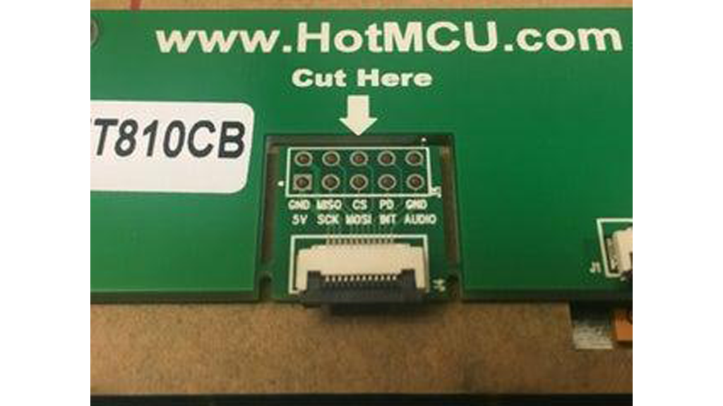
Once you get your screen, you will need to solder headers onto it. The Haoyu screens are great because they come with easy-to-solder through-holes and you have the choice to solder the header directly on the back of the screen or on the end of a small ribbon cable that attaches to a detachable breakout board.
To complete the soldering job, you will want to temporarily disconnect the ribbon cable and remove the PCB board from the back of the panel. Use your fingernail to gently lift the retaining clip on the LCD connector and free the ribbon cable. Then, remove the four screws holding the board in place.
Now solder a 5×2 header (or two 5×1 headers) where you would like them. Cover the back with electrical tape to avoid any shorts. Then, screw the PCB back on and reattach the ribbon cable.
Step 3: Optional: Print the LCD Stand and Add Brass Inserts
I chose to 3D print a stand to hold my LCD panel [1]
The panel comes with four brass inserts; these are meant to be pressed into plastic with heat. As they cool, the little teeth on them bite into the plastic and keeps them from falling out. These inserts are a common way to add durable threads to 3D printed parts.
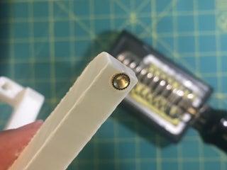
Once the stand was finished printing, I unscrewed the four brass inserts from the panel.
I heated up my iron and held it with the tip angled upward, gently balancing an insert on the tip. I then brought the plastic part down over it and slowly pushed the inserts into the pre-formed holes until they were flush with the surface.
This step works better if you have a soldering iron with a narrow conical tip. If you’ve never done this before, you may want to practice while the iron is cool — you only get one chance to do it right when the iron is hot!
Be careful with this step as the brass inserts get very hot and you don’t want them to fall in your lap. Work on a heat resistant surface and if they do fall off the tip of the iron, resist the temptation to reach for them immediately!
[1] Sources: LCD Stand STL and CAD Files
Step 4: Remove the Film and Mount the Display
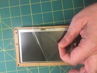
Now, flip over the display and remove the front acrylic frame, then peel off the protective film from the LCD panel (this will enhance the clarity of the display). Use the screws to mount the display on the 3D printed stand.
Step 5: Solder Headers to the LED Module
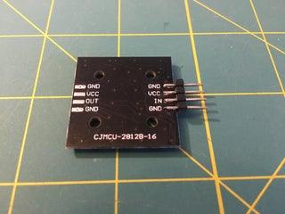
Use side cutters to break off a four-pin length of headers and solder them to the LED module, as shown in the photo. You could also cut lengths of jumper wires in half and solder them on directly, if you prefer.
Step 6: Wire Up the Circuit
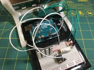
Run three jumper cables from the Arduino to the LED module, as follows:
- 5V to red rail on breadboard
- GND to black rail on breadboard
- IN to pin ~5 on Arduino
For the LCD display, connect:
- 5V to red rail on breadboard
- GND to black rail on breadboard
- SCK to pin ~13 on Arduino
- MISO to pin ~12 on Arduino
- MOSI to pin ~11 on Arduino
- CS to pin ~10 on Arduino
- PD to pin ~9 on Arduino
- AUDIO goes to the audio circuit as shown in the breadboard and schematic
- GND goes to the black rail on the breadboard
From the Arduino:
- Run a jumper cable from the 5V pin to the red rail on the breadboard
- Run a jumper cable from the GND pin to the black rail on the breadboard
With the audio output circuit complete, you can now plug in earbuds headphones or a set of amplified computer speakers to the audio jack.
Design of the Audio Output:
The AUDIO output of the display panel is a digital signal that is not meant to drive a speaker directly. Attempting to do so could damage the panel or the speaker. To provide a proper audio output, you will need to build a conditioning circuit that performs the following tasks:
- Convert the digital PWM (pulse-width modulated) signal into an analog voltage.
- Limits the output current and voltages to safe levels.
The task can be accomplished with two resistors and two capacitors.
I checked the datasheet for the FTDI FT810 chip and found that the AUDIO pin can drive up to 16mA at 3.3V. This means the load must have a resistance of no less than 206 Ohms. To protect the pin against a short, I started by placing a 220 Ohm resistor in series with the AUDIO pin. I then added another 100 Ohm resistor to ground to form a voltage divider. When nothing is connected to the jack, this drops the 3.3V down to a level of approximately 1V, which is safe for line level audio. The 100nF forms a low-pass filter that smooths out the high-frequency PWM noise, while passing audio frequencies. The remaining 1uF capacitor is called a AC coupling capacitor. It blocks DC current from flowing out the audio jack, while letting the audio signal, which is AC, through.
Step 7: Installing the FastLED Library and Running the Code
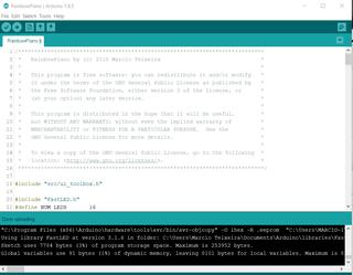
Download the .zip file that contains the Arduino sketch from my github repository.
Open the Arduino IDE and go into “Sketch” -> “Include Library” -> “Manage Libraries…”. Install the “FastLED” library by Daniel Garcia. Then, open the “RainbowPiano.ino” file and upload it to your Arduino Uno!
Step 8: An Overview of the Code
The code makes use of an UI framework I developed in C++. This framework allows you to build an interface out of one of more UI screens. The piano app only has one screen, which is defined by the following code:
class PianoScreen : public InterfaceScreen {
    ...
    public:
      static void onEntry();
      static void onRedraw(draw_mode_t what);
      static void onTouchStart(uint8_t tag);
      static void onIdle();
};

// List all screens in your app in the following table
SCREEN_TABLE {
  DECL_SCREEN(PianoScreen)
};
SCREEN_TABLE_POST

void PianoScreen::onEntry() {
   // Code that executes when a screen is shown
}

void PianoScreen::onRedraw(draw_mode_t what) {
   // Code that runs to draw a screen
}

void PianoScreen::onTouchStart(uint8_t tag) {
   // Code that runs when the user touches the screen
}

void PianoScreen::onIdle() {
   // Code for tasks that run while the screen is active
}
Of these, the most important method is onRedraw(). It paints the user interface by calling methods on the CommandProcessor object, which sends drawing commands to the display panel. The first set of commands clears the screen with black (0x000000):
CommandProcessor cmd;
cmd.cmd(CLEAR_COLOR_RGB(0x000000))
   .cmd(CLEAR(true,true,true));
Then, the code draws the instrument selection buttons on the top of the screen:
#define GRID_ROWS 8
#define GRID_COLS 6
cmd.font(font_small)
     .fgcolor(black)
     .tag(241).button( BTN_POS(1,1), BTN_SIZE(1,1), F("Piano"))
There are a couple things to note here. First, the UI library allows you to layout the interface on a grid. In this case, I lay out my interface on a 6×8 grid. I then set the font and color, followed by a tag.
Each interface button is associated with a tag. When a user clicks on a button, the onTouchStart() method is called with that tag so your can take an appropriate action for that button. The tag precedes the button command, which sends the instructions to position the button labeled “Piano” at position (1,1), while occupying a space of 1×1 on the grid. The code for laying out the piano keys is similar, but happens in a loop.
Later in the code, you find the function that responds to the button with tag 241 being pressed:
void PianoScreen::onTouchStart(uint8_t tag) {
    switch(tag) {
    case 241: highlighted_instrument = tag; instrument = PIANO; break;
    ...
  }
  onRefresh();
}
When the user presses a button, the code modifies some variables to set the instrument to PIANO and then calls onRefresh() to update the screen with the new button highlighted. The highlighting is done by the highlightCallback() function, which during onRefresh() is called for each button to allow you to change the colors of the buttons based on their tags and highlight state.
The code for playing sounds is a bit different:
void PianoScreen::onTouchStart(uint8_t tag) {
  switch(tag) {
    ...
    default:
      // Code for setting the LED colors
      ...
      if(instrument == HIHAT) {
        // Special case for drum kit notes
      } else {
        // Sound off the note
        sound.play(instrument, NOTE_C3 + tag - 1);
      }
      highlighted_note = tag;
  }
  onRefresh();
}
That’s wraps it up for this quick walk-through. I hope this introduction is enough to get you started in designing your own graphical interfaces for your Arduino projects!
Source: Make an Illuminated Rainbow Synthesizer With an Arduino!