From my point of view one of the best ways to get started in electronics is to build your own laboratory power supply. In this instructable I have tried to collect all the necessary steps so that anyone can construct his or her own.
All the parts of the assembly are directly orderable in digikey, ebay, amazon or aliexpress except the meter circuit. I made a custom meter circuit shield for Arduino able to measure up to 36V – 4A, with a resolution of 10mV – 1mA that can be used for other projects also.
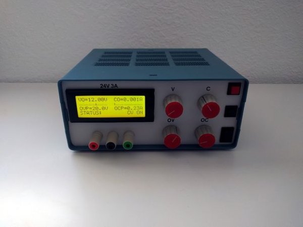
The power supply has the following features:
- Nominal Voltage: 24V.
- Nominal Current: 3A.
- Output Voltage Ripple: 0.01% (According to the specs of the power supply circuit kit).
- Voltage measurement resolution: 10mV.
- Current measurement resolution: 1mA.
- CV and CC modes.
- Over current protection.
- Over voltage protection.
Step 1: Parts and Wiring Diagram
Apart from the Image, I have attached the file WiringAndParts.pdf to this step. The document describes all the functional parts, icluding the ordering link, of the bench power supply and how to connect them.
The mains voltage comes in through an IEC panel connector (10) that has a built in fussible holder, there is a power switch in the front panel (11) that breaks the circuit formed from the IEC connector to the transformer (9).
The transformer (9) outputs 21VAC. The 21 VAC go directly to the power supply circuit (8). The output of the power supply circuit (8) goes directly to the IN terminal of the meter circuit (5).
The OUT terminal of the meter circuit (5) is connected directly to the positive and negative binding posts (4) of the power supply. The meter circuit measures both voltage and current (high side), and can enable or disable the connection between in and out.
Cables, in general use scrap cables you have in house. You can check the internet for appropriate AWG gauge for 3A but, in general the thumb rule of 4A/mm² works, specially for short cables. For the mains voltage wiring (120V or 230V) use appropriately isolated cables, 600V in USA, 750V in Europe.
The series pass transistor of the power supply circuit (Q4) (12) has been wired instead of been soldered to allow an easy installation of the heatsink (13).
The original 10K potentiometers of the power supply circuit has been replaced with multiturn models (7), this makes possible a precise adjustment of the output voltage and current.
Read more: Linear Lab Power Supply with digital meter