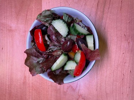
The permutations that fine food has gone through in the last 20 years has been quite amazing. Every nuance has been tweaked and romanced over. Growing up in the midwest where food was taken in merely to prevent bodily collapse until that one day when we went to McDonalds for the first time and I inhaled a burger that was so beyond the usual taste limits that my whole world changed. Things could taste really good! Older with kids I found the burgers nearly intolerable–they had descended to the lower edge of the taste spectrum over the years supplanted by deep dish pizza, barbecue and fresh salmon on a cedar plank.
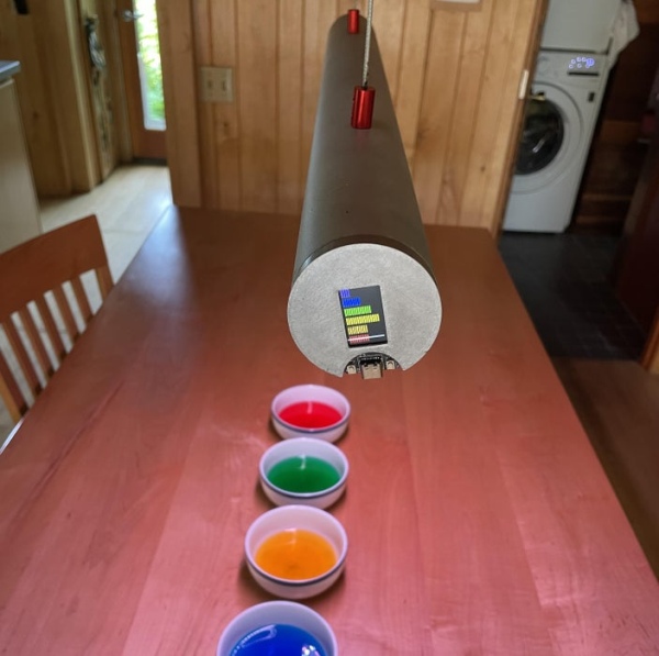
In this instructable I wanted to up the game slightly by extending our taste spectrum with a light spectrum tweak. You can think of it as a Phillips light for food. I built a hanging light outfitted with Neopixels that are controlled by a light sensor that is primed by the food that we place underneath it. In this way the color of the presented food is augmented by a color boost along with the usual wavelengths additional LED’s are recruited to bring up its color subtleties. The Microcontroller presents the color spectrum that was analyzed and using an algorithm balances out the best frequency. You can also subtly adjust this level with a manual override. The system also works for flowers, objects of art and anything else you might want to appear more tempting.
Step 1: Gather Your Materials
The hanging lamp is made out of 52 mm aluminum speed-rail which can be found in any large city with a metal supplier. This is not a requirement and it can also be fabricated out of PVC or any other tube material but of course it would suffer from ugliness.
1. Aluminum Speed Rail–52mm X 26 Inches $20
2. TTGO T-Display ESP32 CP2104 WiFi bluetooth Module 1.14 Inch LCD Development Board $11
3. Adafruit AS7262 6-Channel Visible Light / Color Sensor Breakout $19
4. Adafruit NeoPixel Digital RGB LED Strip – White 60 LED – WHITE $24 about 3 m
5. 1/16 in. x 50 ft. Galvanized Vinyl Coated Steel Wire Rope $10
6. Aluminum Alloy Coupling Shaft Coupler Motor Coupler Connector – 7# $5
7. Power Supply–ALITOVE 5V 8A 40W AC to DC Adapter Power Supply Converter Transformer 5.5×2.1mm $18
Step 2: 3D Print Your Parts
Only a couple of parts need to be 3D printed for the lightPalate. The two end plates–one that contains the Microcontroller and the other a blank disc. One baffle to cover the parts connections on the microcontroller end and the cable attachments inside the housing. They keep the power cables that the unit hangs from making connection with the aluminum housing and shorting it out. They also have built in channels to allow for better cable wrangling. The other part is the insulator that hold the head of the touch control screw from contacting the aluminum housing. The parts are all printed without support out of standard PLA and then painted with Aluminum spray paint to match the housing.
Attachments
- lightWireConnector.stlDownloadView in 3D
- lightAdjustmentCap v1.stlDownloadView in 3D
- Body3.stlDownloadView in 3D
- EndCap.stlDownloadView in 3D
Step 3: Build Your Housing
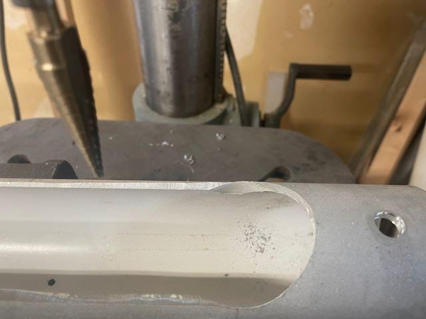
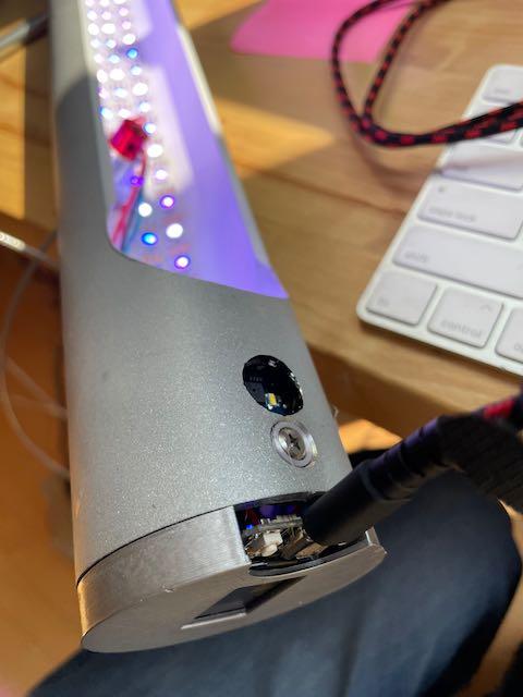
This type of aluminum is very soft and can be easily cut with a metal blade saber saw in a freehand fashion. A straight outline is done of the horizontal cutout. The ends gentle curves are usually outlined with a flexible french curve template to make them smooth. The smoothing of the final curves was done with a dremmel drum sander and a bench sander. Final smoothing was done with a random orbit sander. The housing was then sandblasted with fine grit to give an overall smooth finish both inside and out. Holes were drilled in the top to accommodate the support wires. Additional holes were drilled to fit the opening for the AS7262 6-Channel Visible Color Sensor and the touch control screw-head. These were done with a step-drill. Final painting was done with Valspar top coat flat finish to the outside of the housing and the inside was painted with a flat white spray paint to reflect light.
Step 4: Add Neopixels
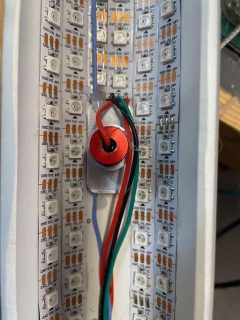
The Neopixels are stripped of their silicon covers to allow them to be directly mounted to the inside of the lightPalate housing. Approximately 3 meters of neopixels was used in the project but you can increase this to bolster the lighting intensity as much as you want. The NeoPixel strands are glued directly to the painted inner liner with E7000 glue. You don’t really have to worry about the strands shorting out with contact with metal except at the ends where the wires are attached. These areas are problematic and should be covered heavily with liquid electrical tape insulator fluid–a great product. Follow the basic rules of installing and connecting NeoPixels that can be found here: https://learn.adafruit.com/adafruit-neopixel-uberguide. The mounting pads for the connectors that you 3D printed in the last section can be glued over the holes for the stranded wire hanging mounts. The stranded wires are fed through the mounting holes and are then soldered to lengths of connection wires for the positive and negative feeds for the computer and the NeoPixels. These are carefully sealed in shrink wrap and a red anodized coupler shaft connector holds it in place with a set screw and slid into the 3D printed housing.
Step 5: Wire It
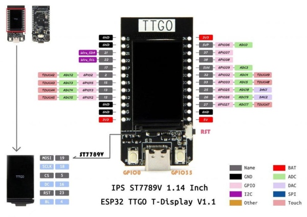
The wiring is pretty simple. The AS726 6 channel sensor is connected via I2C to the TTGo unit and also powered from the 3V takeoff. This great guide from Adafruit will help you if you have any questions regarding the hook-up and function of this unit. I tried the more basic color sensor from Adafruit that outputs in RGB format and found it inadequate for this use and have also tried the next higher unit: Adafruit AS7341 10-Channel Light / Color Sensor Breakout but unfortunately could not get it to give consistent and accurate output–even trying the library from DFRobot. The sensor has built in pull-up resistors so all you have to do is connect SDA to 21 and SCL to 22 and the Vin to 3 volts and ground. The NeoPixel control line is 33–connect this with a resistor as described in the NeoPixel uber guide. TouchRead(2) is the control line to activate the software to do the color scan of your food object and should be connected to pinout 2. The control buttons are already connected on the board to 0 and 35 and these do the software control of the manual setting of the colors. I have also added an on/off touch control line to line 13 for touchRead(4). A large capacitor (see guide) is connected between the power supply wires. The power is connected to the NeoPixels and the 5volt line on the microcontroller. All grounds are connected. The hanging support cables are then connected to the 5.5 x 2.1 +/- connector for the power supply. I found it easier to solder larger caliber silicon wires as intermediaries instead of cramming the stiff cables into the holes in the connector. I build a solid support bar out of aluminum stock with to attach the cables to in the ceiling.
Step 6: Putting It Together
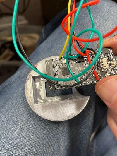
The microcontroller is E7000 glued into the 3D printed housing. The end cap is glued in. The AS726 is glued into position so both its sampler housing and the lighting LED are within the opening to allow sampling. The touch-screw is placed within its plastic housing that fits into the prior drilled hole. It is important that the wire connecting the touchSensor circuit is connected to the end of this screw without contacting the body of the lamp. The remainder of the wiring is sequestered behind the 3D printed baffle plate and the end cap with the microcontroller is glued into position.
Step 7: Program It
The program uses the Adafruit AS726x.h library for analysis of the output from the light module. There are six color outputs from the library that are defined in an array of sensor values that include violet, blue, green, yellow, orange and red. The overall output of the Neopixels is done through the FastLED.h library. (I was so sorry to learn of the loss of the gentleman that did the development of this wonderful library on that scuba boat on Catalina Island—love his work!). The void setup() sets up the FastLED network and sets to two pushbuttons to a primary high state and initializes the TFT screen. The AS726x.h sensor is also activated. The first section of the loop function has a state machine that polls the pushbuttons to see if you want to manually set the light level and to check if you activated the color scanner for the food items. On activation of the scan mode a set of red LEDs moves down the lamp to warn the scan is coming. AMS.drvOn sets the LED to light the scan and the scanning is completed and the information dumped into the array lightValue. The function maxValue is called that finds the highest level in the array and takes the values on either side and uses a balanced averaging algorithm that adds or subtracts spectrum levels based on their value. FinalLight represents the H in the HRV value sent to the FastLED library for display. R and V are left at 255. Every third LED is left full white to give a balanced but augmented lighting to the object–so as not to disrupt normal viewing for the rest of the table. The last portion is the TFT display algorithm which places the six channels of light and displays a red bar representing the finalLight average. Manually adjusting the display changes the chosen output bar to white.
Step 8: Using It
Plug it in and the scanner activates to scan the background light and the lights come on. To scan a particular food or object just place it under the scan-hole and tap on the touch pad just next to it. A running row of Red LEDs will traverse the lamp to the scanner end and the scanner LED will flash for a moment and absorb the color spectrum which will then be displayed on the TFT screen of the microcontroller. The lights will adjust to the optimum color and you are set. To adjust a manual color push either of the two buttons on the ESP and the spectrum can be adjusted to the most pleasing color wash.
The color sensitivity of your eyes is a complex adjustment system that is sometimes different from the more unambiguous spectral sensitivities of the machine read values. This misalignment is often found when scanning objects and leads to some discontinuity in what to expect. Color augmentation is done at the chief reflectance color of the object–different effects can be done if the color wheel is adjusted to complimentary colors(easily done in software) or FastLED can be modified using custom color pallets which can be chosen for the types of items you would be most interested in showing with great subtlety. See:https://learn.adafruit.com/twinkling-led-parasol/a…
Since you are using an ESP-32 you can easily program a Bluetooth adjustment App to modify your color choice on the fly. And a even neater goal would be an App that takes a photo of your feast and can pinpoint on the screen the colors that you upload to the ESP via bluetooth. These apps are already available for color analysis so it shouldn’t be that hard to do. What is hard is trying to get this perfect salmon color out of anything except Alaska wild caught Sockeye Salmon!
Source: Light Palate–Selective Lighting for Your Next Feast