Summary of Larson Scanner with Relay Module using Arduino
This article details a project using an Arduino board to control an 8-channel relay module. The setup involves mounting a sensor shield on the Arduino and connecting it to the relay module via specific pins, powered by an 11.1V battery. The author provides code to create a "Knight Rider" light effect, demonstrating how different software can be applied to the same hardware for various applications like controlling fans or appliances.
Parts used in Larson Scanner with Relay Module using Arduino:
- Arduino board
- Sensor shield
- 8-channel relay module
- Wires
- 11.1V battery
This time I’ll show how I used an Arduino to control a relay module with eight channels.
Arduino in offers several advantages such as:
– Open source;
– Easy programming;
– You can assemble your own board;
– Is supported on various forums on the Internet;
– Has several “shields” (facilitates the use of it with sensors, for example.)
– Among others.
The idea I had was to create a simple programmable hardware. Where only would create a different software for each application.
Just as our computer. What we do (generally) is add a software The hardware remains the same.
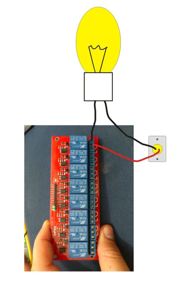
We can control larger loads within the limits of current and voltage relays. For example, connecting a ventilator, an appliance, among others.
Step 1: Materials
Below the list of materials:
– Arduino board;
– Sensor shield;
– 8-channel relay module;
– Wires;
– 11.1V battery
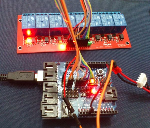
Step 2: Mounting
Mount the sensor shield on Arduino Boar and connect the shield to the relay modulde following the statement below.
link:
module -> Shield
in1 -> pin 13
in2 -> pin 12
in3 -> pin 11
in4 -> pin 10
in5 -> pin 9
in6 -> pin 8
in7 -> pin 7
in8 -> pin 6
Take care not to invert the wires.
The battery is connected as follows: A wire was added to the negative pole connected to GND and the shield and the other of the DC relay module.
The module was connected to the wire GND which is the same shield plate Arduino.
Step 3: Connecting and Programming
After assembling the hardware, just plug in and program the Arduino.
The following program was done to test the relay module. Works like the lights of the “Knight Rider”. The effect is quite interesting. Hope you enjoy.
Software:
Software:
int pinArray[] = {13, 12, 11, 10, 9, 8, 7, 6};
int count = 0;
int timer = 50;
void setup(){
for (count=0;count<7;count++) {
pinMode(pinArray[count], OUTPUT);
}
}
void loop() {
for (count=0;count<7;count++) {
digitalWrite(pinArray[count], HIGH);
delay(timer);
digitalWrite(pinArray[count + 1], HIGH);
delay(timer);
digitalWrite(pinArray[count], LOW);
delay(timer*2);
}
for (count=7;count>0;count–) {
digitalWrite(pinArray[count], HIGH);
delay(timer);
digitalWrite(pinArray[count – 1], HIGH);
delay(timer);
digitalWrite(pinArray[count], LOW);
delay(timer*2);
}
}
– Sensor shield;
– 8-channel relay module;
– Wires;
– 11.1V battery
For more detail: Larson Scanner with Relay Module using Arduino
- What are the advantages of using an Arduino?
It is open source, easy to program, allows you to assemble your own board, has internet forum support, and works with various shields. - How do I connect the relay module inputs to the Arduino pins?
Connect in1 to pin 13, in2 to pin 12, in3 to pin 11, in4 to pin 10, in5 to pin 9, in6 to pin 8, in7 to pin 7, and in8 to pin 6. - How should the battery be connected to the system?
A wire connects the negative pole to GND on both the shield and the DC relay module, while another wire connects the positive side. - Can this setup control larger loads?
Yes, you can control larger loads like ventilators or appliances within the current and voltage limits of the relays. - What does the provided software program achieve?
The program creates a Knight Rider light effect that cycles through the relay channels. - Which pins are defined as output in the setup function?
Pins 13, 12, 11, 10, 9, 8, and 7 are set as output. - What is the value of the timer variable in the code?
The timer variable is set to 50 milliseconds. - Does the code loop in both forward and backward directions?
Yes, the loop first iterates from count 0 to 7 and then from count 7 down to 0.