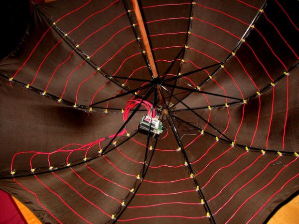
The LED Umbrella with Arduino combines an umbrella, an 8×10 LED matrix and an Arduino microcontroller to create a controllable, programmable LED experience in the privacy of your own umbrella. This project was inspired by the Electric Umbrella by sockmaster and a number of LED matrix instructables on this site, particularly this very complete one by barney_1.
Anyone undertaking this project should have access to standard soldering tools — pliers, diagonal cutters, wire cutters and strippers, soldering iron and solder, multimeter — and have experiencing working with the Arduino. The Arduino setup is not difficult and a program including several different animations of the LEDs is included in this instructible.

Video is on the way! Sample code (see last step) is also on the way, too. The code that I do have does not take advantage of the pushbutton switch and I am working on that now.
Step 1: Parts
There are very few parts for this project and they are mostly generic. They can be easily obtained from any number of online retailers — Adafruit Industries, DigiKey, Jameco, and All Electronics, among many others. Substitute as seems reasonable.
Electronics
1 x Microcontroller — Arduino Diecimilia
1 x Umbrella
1 x MIC2981 — 8-channel, high-voltage, high-current source driver array — 576-1158-ND
1 x Protoshield for Arduino with tiny breadboard — Adafruit Industries
80 x LED — many options are possible
8 x resistors — depends on choice of LED and source voltage
Wire
Lots of wire is needed for this project. Each rib of the umbrella has a black wire (for the cathodes of the LEDs) and each circle of LEDs around the umbrella requires a full length of red wire (for the anodes of the LEDs). Some is also necessary to return the ends of the chains back to the Arduino.
24 feet black wire for cathode chains (follow ribs back to center)
70 feet red wire for anode rings (rings around umbrella)
Miscellaneous
Standard male headers —
Heat shrink tubing 1/16″ — about seven feet of tubing is needed
Tactile switch — Off-Mom
Patience
…and soldering skills. The matrix of LEDs has to be carefully constructed and the anodes and cathodes insulated from one another with heat shrink tubing. This can take a while.
Step 2: Afterthoughts — Forewarned is Forearmed
Umbrella
Don’t use your best umbrella! Or even someone else’s best umbrella. The umbrella is committed to the project and, while you could take the LED matrix out, you won’t want to by the time you are finished.
Placement
Although the LEDs provide a personalizable experience under the umbrella, they are not particularly visible from outside/above the umbrella. Consider whether you want the LEDs on the outside of the umbrella. They would be far more visible and the installation would be a lot easier. You would have to poke holes in the fabric to feed the wires down into the Arduino. Style in this case trumps waterproofing.
LEDs
Pick a nice color before you put a lot of time into making this thing. LEDs are apparently cheaper on eBay than through catalogs, so explore your options.
Wire
Smaller gauge or multi-stranded wire is probably better than AWG xxx solid wire. I used solid wire and it makes folding up the umbrella almost impossible. Also, I wouldn’t use red wire for the anode rings. I would have picked a darker color that is less visible.
Step 3: Design Considerations
Arduino
I chose to use the Arduino rather than a different Atmel AVR microcontroller to make this project accessible. With the Arduino, there is no need to design a custom board and programming and customization is much easier with the Arduino platform. The only downside of the Arduino is that it is big and doesn’t fit well into an umbrella. The benefits, however, outweigh the costs.
This project is based on the Arduino Diecimilia but (I think) the pinouts are the same on newer versions. In any case, if you undertake this project, make sure you have a clear understanding of the states and pins of the Arduino model you are using. This will make any changes between what is describe here and what you need to do easy to implement.
MIC2981
The MIC2981 chip from Micrel can power 8 chains of LEDs. This means that the 8 circular rows/rings of ten LEDs going around the umbrella have their anodes linked to the MIC2981 (one pin powering each row/ring) and the LEDs in the chains along the ribs (the columns) have their cathodes linked to a pin on the Arduino. This allows for the possibility that the 10 LEDs in a row/ring are simultaneously on with enough current to uniformly light them.
This chip is currently not used in this project. I have plans to use it to power and brighten the LED rings.
Proto Shield for the Arduino from AdaFruit Industries
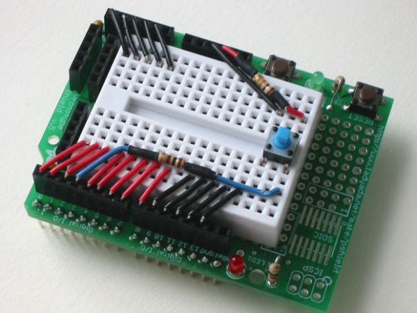
I used this protoshield with a tiny breadboard so that I could detach the Arduino from the umbrella for other projects. The tiny breadboard has just enough room for the connections needed for this project.
Step 4: MockUp
In order to make sure I understood how the LED array should be fabricated, I made a 3×3 array to see if the soldering and programming would work. They did! So I decided to go ahead with the project. If you are sure you understand the LED array, skip this step. Otherwise, invest a couple of LEDs, some wire, shrink wrap, and an hour or so in making the 3×3 array and testing it out. The details of making the array are in the following steps but are applicable to the mockup.
To create the 3×3 LED matrix, follow and modify the steps Making the LED Matrix that describe the full matrix.
The sample code below for the mockup does not take advantage of the MIC2981 (I wrote it before I had one :-). Each LED is illuminated in turn. This works for a 3×3 array but does not scale well. [Actually, it scales reasonably well to the full matrix but the LEDs are a bit dim.]
Step 5: Making the LED Matrix — Preparing the Parts
LEDs
Prepare the LEDs by bending their leads. The following orients the LEDs with their flat edges facing in the same direction. The choice is arbitrary, but standardizing an orientation reduces the risk of error.
Hold the LED with its flat side (cathode side) turned to your right. Bend the cathode toward you. This points the cathodes to ground, the direction electricity wants to flow :-). Create the bend about 1-2 mm below the bottom of the LED. This will allow the LED to stand proud of the wire.

The anode will be bent to the left after the cathodes are soldered into place. This will prevent confusion when soldering. The two leads should form a right angle with the cathode pointing towards you and the anode pointing toward your left.
Heat shring tubing
Cut two 1/2″ long pieces of 1/16″ heat shrink tubing for each LED. That’s one hundred sixty pieces and requires about seven feet just for these. Cut an additional eighteen (18) pieces for the headers.
Wire
Cut black wires equal in number to the ribs on the umbrella. Make them enough longer than the ribs so that there is enough wire to create the headers that connect to the Arduino.
There are 8 rings of LEDs that go around the umbrella (this is the number of output pins on the MIC2981) so each cathode chain or column will consist of 8 LEDs. Lay the wires out and mark the locations for the LEDs along the ribs. Spacing at this point establishes the distance between the concentric rings.
Strip a small piece of insulation (about 3mm) at each point. Cut through the insulation with wire strippers at two places about one-quarter of an inch apart. Then crush the insulation with pliers and cut the insulation out with a utility knife or pull it out with your fingers. In each open space, put a small amount of solder. This is in preparation for soldering the LED cathodes to these spots.
For more detail: LED Umbrella with Arduino
