Summary of LED Dot Matrix Display using an Arduino
This project demonstrates how to control an 8x8 LED dot matrix display using two sets of shift registers and multiplexing. By rapidly scanning rows, the system creates the illusion of a steady image, such as an animated heart, without requiring excessive microcontroller pins. The article explains the wiring logic of common anode matrices and details how persistence of vision allows individual LEDs to appear lit simultaneously when scanned at over 100Hz.
Parts used in the LED Dot Matrix Display Project:
- 1 LED matrix
- 8 resistors 1k ohm
- 8 557 transistors
- 1 ULN2803 IC
- Arduino
- 2 74HC595 shift register
- 2 Bread board
- Connecting Wires
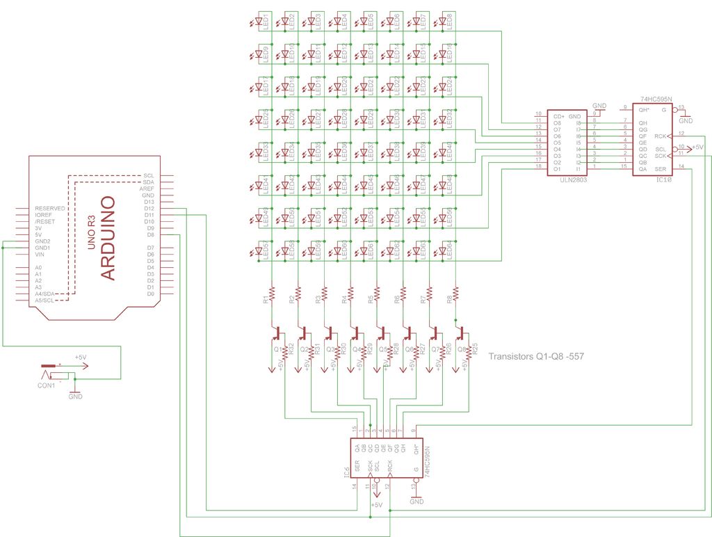
In this project, you shall again use two sets of shift registers. These will be connected to the rows and
columns of the dot matrix display. You will then show a simple object, or sprite, on the display and
animate it. The main aim of this project is to show you how a dot matrix display works and introduce the
concept of multiplexing because this is an invaluable skill to have.
Step 1: Things Required
for this project you will require -:
1. 1 LED matrix
2. 8 resistors 1k ohm
3. 8 557 transistors
4. 1 ULN2803 IC
5 Arduino
6. 2 74HC595 shift register
7. 2 Bread board
8. Connecting Wires
Step 2: Working
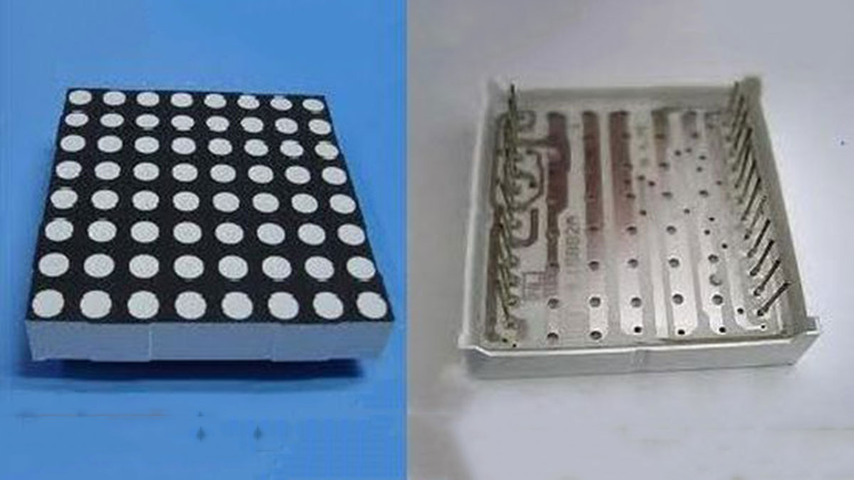
matrix such that either the anode or cathode of each LED is common in each row. In other words, in a
common anode LED dot matrix unit, each row of LEDs would have all of their anodes in that row wired
together. The cathodes of the LEDs would all be wired together in each column. The reason for this will
become apparent soon.
A typical single color 8×8 dot matrix unit will have 16 pins, 8 for each row and 8 for each column.
The reason the rows and columns are all wired together is to minimize the number of pins required.
If this were not the case, a single color 8×8 dot matrix unit would need 65 pins, one for each LED and a
common anode or cathode connector. By wiring the rows and columns together, only 16 pins are
required.
However, this now poses a problem if you want a particular LED to light in a certain position. If, for
example, you had a common anode unit and wanted to light the LED at X, Y position 5, 3 (5th column,
3rd row), then you would apply a current to the 3rd Row and ground the 5th column pin.
The LED in the 5th column and 3rd row would now light.
Now let’s imagine that you want to also light the LED at column 3, row 6. So you apply a current to
the 6th row and ground the 3rd column pin. The LED at column 3, row 6 now illuminates. But wait…the
LEDs at column 3, row 6 and column 5, row 6 have also lit up.
This is because you are applying power to row 3 and 6 and grounding columns 3 and 5. You can’t
turn off the unwanted LEDs without turning off the ones you want on. It would appear that there is no
way you can light just the two required LEDs with the rows and columns wired together as they are. The
only way this would work would be to have a separate pinout for each LED, meaning the number of pins
would jump from 16 to 65. A 65-pin dot matrix unit would be very hard to wire up and control because
you’d need a microcontroller with at least 64 digital outputs.
Is there a way to get around this problem? Yes there is, and it is called multiplexing (or muxing).
Multiplexing is the technique of switching one row of the display on at a time. By selecting the column
that contains the row that contains the LED that you want to be lit, and then turning the power to that
row on (or the other way round for common cathode displays), the chosen LEDs in that row will
illuminate. That row is then turned off and the next row is turned on, again with the appropriate
columns chosen and the LEDs in the second row will now illuminate. Repeat with each row till you get to
the bottom and then start again at the top.
If this is done fast enough (at more than 100Hz, or 100 times per second) then the phenomenon of
persistence of vision (where an afterimage remains on the retina for approx 1/25th of a second) will mean
that the display will appear to be steady, even though each row is turned on and off in sequence.
By using this technique, you get around the problem of displaying individual LEDs without the
other LEDs in the same column or row also being lit.
By scanning down the rows and illuminating the respective LEDs in each column of that row and
doing this very fast (more than 100Hz) the human eye will perceive the image as steady and the image of
the heart will be recognizable in the LED pattern.
You are using this multiplexing technique in the Project’s code. That’s how you’re to display the
heart animation without also displaying extraneous LEDs.
2. 8 resistors 1k ohm
3. 8 557 transistors
4. 1 ULN2803 IC
5 Arduino
- How does multiplexing solve the problem of lighting specific LEDs?
Multiplexing switches one row on at a time by selecting the correct column and turning that row's power on, then quickly moving to the next row. - Why is multiplexing necessary for an 8x8 matrix?
It avoids the need for 65 separate pins by allowing only 16 pins to control the entire grid through rapid row scanning. - What happens if you apply power to multiple rows simultaneously?
Unwanted LEDs in the same columns will also light up, making it impossible to isolate specific pixels. - At what speed must the rows be scanned to appear steady?
The rows must be turned on and off more than 100 times per second (100Hz). - What visual phenomenon makes the animation appear steady?
Persistence of vision causes an afterimage to remain on the retina for approximately 1/25th of a second. - How are the rows and columns wired in a typical 8x8 unit?
In a common anode unit, all anodes in a row are wired together, while cathodes are wired together in each column. - Can you light just two specific LEDs without affecting others?
Yes, by using multiplexing to scan rows individually rather than applying constant power to multiple rows. - What is the main aim of this project?
To show how a dot matrix display works and introduce the concept of multiplexing.