Summary of Color Changing Night Light with ATtiny using Arduino
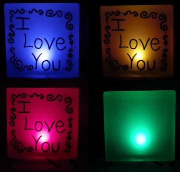
This project is a dark-activated, color-changing night light designed as a gift for children. It uses an ATtiny85 microcontroller to control an RGB LED that fades through colors when ambient light drops below a threshold detected by an LDR. The circuit is built on a perfboard and powered by a recycled wall wart. The device is housed in a frosted hobby glass block for a soft glow.
Parts used in the Color Changing Night Light:
- 22uf capacitor
- 10nf 103 capacitor
- 7805 voltage regulator
- LDR (Light Dependent Resistor)
- 2 – 10K resistor
- 2 – 100ohm resistor
- 220ohm resistor
- RGB LED (common anode)
- ATtiny85
- 8 pin socket
- Wire
- Perfboard
- Wall Wort Plug about 7-18V
- Hobby Glass Block
- Hot Glue Gun
- Glass Block Stand
- Glass Frosting Spray Paint
- Paint Pen/Sharpie
- Computer
- Arduino
- Breadboard
- Jumper Wire
- Wire Stripper
- Voltmeter
- Soldering Iron
- Solder
- Razer Blade
I wanted to create something for my wife as a present and this is what I came up with. This is a dark activated color changing night light. It has a sensor that can tell when the room light is turned off. This then will light a RGB LED and slowly fade through different colors. Its brains is a ATtiny85, but you could also use an Arduino. We have little boys that would appreciate this on at night.
Step 1: Parts
Parts for the Circuit:
- 22uf capacitor
- 10nf “103” capacitor
- 7805 voltage regulator
- LDR (Light Dependent Resistor)
- 2 – 10K resistor
- 2 – 100ohm resistor
- 220ohm resistor
- RGB LED (The one I got from RadioShack has a common anode.)
- ATtiny85 (can be bought at www.sparkfun.com)
- 8 pin socket
- Wire
- Perfboard
- Wall Wort Plug about 7-18V (test this with a voltmeter, don’t trust the label)
Everything can bought at RadioShack but the ATtiny85.
Don’t buy the Wall Wort Plug. You or someone you know probably has one they don’t use, like the plug to charge a cell phone… When possible, recycle.
Parts for the Light:
- Hobby Glass Block
- Hot Glue Gun
- Glass Block Stand
- Glass Frosting Spray Paint
- Paint Pen/Sharpie
Other Items:
- Computer
- Arduino
- Breadboard
- Jumper Wire
- Wire Stripper
- Voltmeter
- Soldering Iron
- Solder
- Razer Blade
Assumptions:
- That you at least have a little experience programing an Arduino and know how to solder on a perfboard. If you are an absolute beginner you may need some help.
Step 2: Programing
There are many great sites and other instructables that give step by step instructions on how to program a ATtiny85 with a Arduino. You could just use the Arduino instead of the ATtiny85 if you like. You would just have to change the pin locations in the code. The reason I used the ATtiny85 was because it is a cheap chip and I wanted the smaller form factor. The ATtiny85 can be programed on a shield if you have one or right on a breadboard.
Check out:
- http://www.instructables.com/id/Program-an-ATtiny-with-Arduino/
- http://www.instructables.com/id/8-Pin-Programming-Shield/
Here is the sketch/program:
// attiny85 RGB LED rainbow fade with LDR
//By Matt Jenkins
const int redPin = 2;
const int grnPin = 4;
const int bluPin = 1;
int sensorPin = 3; // select the input pin for the ldr
unsigned int sensorValue = 0; // variable to store the value coming from the ldr
void setup()
{
pinMode(redPin, OUTPUT);
pinMode(grnPin, OUTPUT);
pinMode(bluPin, OUTPUT);
//Start Serial port
//Serial.begin(9600); // uncomment for Serial port // start serial for output – for testing
}
void loop()
{
// read the value from the ldr:
sensorValue = analogRead(sensorPin);
if(sensorValue>400){ // set the LED OFF // lower number for on when darker or raise number for on when brighter
digitalWrite(redPin, HIGH);
digitalWrite(grnPin, HIGH);
digitalWrite(bluPin, HIGH);
}
else{ //Fade through Colors
redtoyellow();
yellowtogreen();
greentocyan();
cyantoblue();
bluetomajenta();
majenatored();
}
delay (30);
// For DEBUGGING – Print out our data, uncomment the lines below
//Serial.print(sensorValue, DEC); // print the value (0 to 1024)
//Serial.println(“”);
//delay(500);
}
void redtoyellow()
{
digitalWrite(redPin, HIGH);
digitalWrite(bluPin, LOW);
// fade up green
for(byte i=1; i<100; i++) {
byte on = i;
byte off = 100-on;
for( byte a=0; a<100; a++ ) {
digitalWrite(grnPin, HIGH);
delayMicroseconds(on);
digitalWrite(grnPin, LOW);
delayMicroseconds(off);
}
}
}
void yellowtogreen()
{
digitalWrite(grnPin, HIGH);
digitalWrite(bluPin, LOW);
// fade down red
for(byte i=1; i<100; i++) {
byte on = 100-i;
byte off = i;
for( byte a=0; a<100; a++ ) {
digitalWrite(redPin, HIGH);
delayMicroseconds(on);
digitalWrite(redPin, LOW);
delayMicroseconds(off);
}
}
}
- Computer
- Arduino
- Breadboard
- 220ohm resistor
- RGB LED
- ATtiny85
For more detail: Color Changing Night Light with ATtiny using Arduino
- What is the main component used to detect room darkness?
An LDR (Light Dependent Resistor) detects when the room light is turned off. - Can I use an Arduino instead of an ATtiny85?
Yes, you can use an Arduino but must change the pin locations in the code. - Why did the author choose the ATtiny85 chip?
The author chose it because it is cheap and offers a smaller form factor. - How does the RGB LED behave when the room is bright?
The LED turns off if the sensor value is greater than 400. - What type of RGB LED was used in this project?
A common anode RGB LED from RadioShack was used. - Where can I buy the ATtiny85 chip?
The article states the ATtiny85 can be bought at www.sparkfun.com. - What is the recommended power source for the circuit?
A Wall Wort Plug rated about 7-18V is recommended. - How should the light be housed for a better effect?
The light is placed inside a Hobby Glass Block sprayed with Glass Frosting Spray Paint. - Does the code include a feature to print debug data?
Yes, the sketch has commented lines to enable Serial port output for testing. - What skills are assumed for someone building this project?
Experience programming an Arduino and knowing how to solder on a perfboard are assumed.