Summary of LED Chaser Game
This article details the creation of an interactive LED Chaser Game using an Arduino Uno, a 555 timer, and a decade counter. Players must press a button when a specific color (red, yellow, or green) flashes on the LEDs, matching a target color displayed on a 4-digit seven-segment display. The project involves wiring components to control the chaser speed and score tracking, followed by coding logic to manage random color selection, input validation, and score updates on the display.
Parts used in the LED Chaser Game:
- 555 Timer
- Johnson's Decade Counter
- Arduino Uno
- 4 Digit Seven Segment Display
- Potentiometer (10k)
- Assorted LEDs (Red, Green, Yellow)
- Pushbutton
- Resistors (560 Ohms, 10K Ohms, 1K Ohms)
- Electrolytic Capacitor (10 uF)
- Wires
- Breadboard
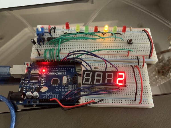
Hello, my name is Vigas Balachandran and on this instructable, I will be presenting my final project. For this project, I have created a LED chaser game. In this game, the LEDs will be flashing in consecutive order. On the serial monitor on the arduino, you will be given a colour. With the given, you will need to press the button at the same time the LED chaser passes over that colour. For example, if you are given red, you will need to press the pushbutton right as it passes over red. This circuit works through the usage of a 555 timer, a decade counter, and an arduino. The 555 timer and decade counter control the LED chaser, and then the arduino receives the signal from the LEDs and compares it to the push button. Now that you know how this project works, let’s move onto the materials.
Step 1: Materials
For this project, here are the materials you will need…
1. 555 Timer x1
2. Johnson’s Decade Counter x1
3. Arduino Uno x1
4. 4 Digit Seven Segment Display x1
5. Potentiometer (10k) x1
6. Assorted LEDs (Preferably red, green and yellow to make the project easier to complete) x7
7. Pushbutton x1
8. Resistors (x8 560 Ohms, x1 10K Ohms, x1 1K Ohms)
9. Electrolytic Capacitor (10 uF) x1
10. Wires
Lastly but not least, is a breadboard, but that is optional and will help with managing your wiring. Now that all the materials are listed, let’s go to the wiring.
Step 2: Wiring
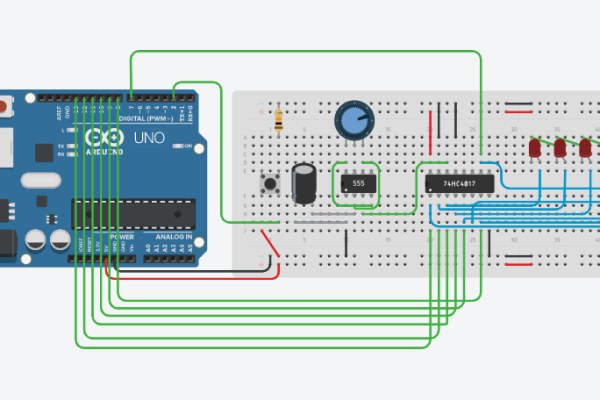
For the wiring, the Tinkercad and the schematic above can help with connecting all of the components together.
1. Connecting the Power Source
Since there will be multiple components that require both power and ground, the first thing to do is to connect the VCC and GND to the breadboard so that it flows throughout.
2. Building the LED Chaser: Part 1 (555 Timer)
The entire basis of this project is the LED chaser, and without it, there would be no point in the game. Using either the schematic or Tinkercad above, you will be able to build an LED chaser. To start off, you need to connect power of the 555 timer to VCC and ground of the timer to ground. Next you want to connect pin 2 (trigger) and pin 6 (threshold) of the timer together. After that, you need to connect pin 4 (reset) to pin 8 (power), so that pin 4 gets power. Next, you need to place a 10k ohm potentiometer on pin 8, pin 7 (discharge), and pin 6. This potentiometer will allow you to change the speed of the LED chaser. The last part of the 555 timer is a electrolytic capacitor, which connects both pin 1 (ground) and pin 2. These are all of the main connections of the 555 timer. There is one last connection, but that brings us to the next component, the decade counter.
3. Building the LED Chaser: Part 2 (Decade Counter and LEDs)
Continuing off of the previous paragraph, the last connection of the 555 timer is pin 3 (output), which connects to pin 14 (clock) of the decade counter. Since the 555 timer is configured in the astable mode, it sends that pulse to the decade counter, which will soon send it to the LEDs. Now for the decade counter, you need to start off just like the 555 timer, and connect both power and ground to pin 16 (power) and pin 8 (ground). Other than the main outputs, there are two other connections, being pin 15 (reset) and pin 13 (clock enable) to ground. All that’s left to do is connect all of the outputs depending on how much LEDs you are using. Since I used 7 in my project, I connected outputs 1-7 to the anodes on the LEDs (look at Tinkercad above). The last thing you need to do before completing the LED chaser is connect ground to each of these LEDs. In my circuit, I have a 1k Ohms resistance going through each of the LEDs.
4. Connecting the Pushbutton, 4 Digit 7 Segment Display, and connecting all of the Arduino Pins
Now that the LED chaser is built, the last part of the wiring is to connect all of the Arduino Pins, and connect pushbutton as well as the 4 digit 7 segment display. Listed below are all the Arduino Connections.
Pin 2 = Button
Pin 3 = f
Pin 4 = a
Pin 5 = d3
Pin 6 = b
Pin 7 = output 5
Pin 8 = output 4
Pin 9 = output 7
Pin 10 = output 3
Pin 11 = output 1
Pin 12 = output 2
Pin 13 = output 6
Pin A0 = e
Pin A1 = d
Pin A2 = p
Pin A3 = c
Pin A4 = g
Pin A5 = d4
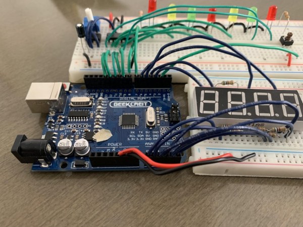
In the image below, you can see where the pins are connected. Furthermore, the schematic above has a detailed view of which pins connect to which components. In the connected pins, you might notice that some pins are connected to the output. These pins are connected to the output on the decade counter, to receive a pulse to compare with the button. It’s with this that we will be able know when to add the score, by comparing the LEDs and the pushbutton. On the 4 digit seven segment display, there are resistors attached to the pins. All of these resistors are 560 Ohms and reduce the voltage going into the pins on the display. Lastly to finish off the wiring, there is the pushbutton. The pushbutton has 4 pins, the bottom left connecting to power, the top right connecting to ground through a 10k Ohm resistor, and the bottom right pin connecting to the Arduino pin. Now that the wiring is complete, let’s move onto then coding.
Step 3: Image of Arduino Pin Connections
Step 4: Coding: Part 1 (Variables)
Before I start explaining the code, I will leave the file to the code at the beginning of this section.
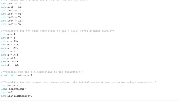
To start off in the code, you will need to initialize all of you variables. By initializing the variables, you will be able to control the pins of the Arduino and much more. All of the variables with the LED in it are the variables that are taking the pulse from the output of the decade counter. The variables with the letters are the variables that are controlling the pins of the 4 digit 7 segment display. All of the variables are set to equal the pin that they are connected to. The picture above shows all of my variables.
Step 5: Coding: Part 2 (Setup Function)
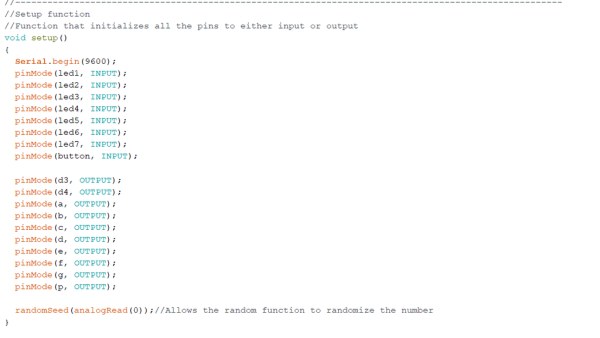
Now that all of your variables are initialized, you need to set them to input or output to actually connect the pin. You can do that by doing the following.
pinMode((Variable name),(Input or Ouput));
For example, for the first LED, I have that set as input, because that pin is receiving the pulse from the decade counter. In fact, all of the LED variables need to be set as input because they are receiving the pulse from the decade counter. All of the 4 Digit 7 Segment variables need to be set as output because they are outputting the signals to the pins. For the pushbutton, that needs to be set as input because it is also receiving a signal from the click. Lastly, there is randomSeed(analogRead(0)). This piece of code allows the random number generator (later on in the code) to actually generate random numbers. By adding all of the variables to the setup function, you are essentially incorporating the components into the circuit.
Now that the setup function is done, we can move on to the biggest part of the code, the loop function.
Step 6: Coding: Part 3 (Loop Function)
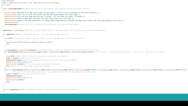
Now onto the largest part of the code, the loop function, where the main code takes place. The first part that I have added is an initial message, which is completely optional. I do so by adding a message in the serial monitor, that is inside a while loop with the initialMessage variable. The condition is that if the variable is 0, the message is displayed. I have it so that inside the while loop, after the message is displayed, I add one to the variable so that the message is only played once.
Now onto the actual code for the game. To start off, I set the randColour variable to equal a random number from (1-3 (Including those)). Then, I have 3 main if statements, that run based off of the randColour variable. If the randColour variable equals 1, then the code for the red colour is run. If the variable is 2, the code for the yellow colour is run. Lastly if the variable is 3, then the code for the green colour is run. The code within each is essentially the same, however when comparing the button to the LEDs, the LED numbers are different.
To start, I have another while loop similar to the first one, to run the message of the colour that was given. This message is only displayed once, and displayed again after the button is pressed.
Next, I initialize a variable called buttonState and set that to read the value of the pin connected to the button.
int buttonState = digitalRead(button);
After that, I have an if statement that checks if the button is equal to HIGH, which means that the button is pressed. In the same if statement, it checks to see if the LEDs are on. Now this is the part that will vary from the three colours. The if statement should look like the following…
if ((buttonState==HIGH) && ((digitalRead(led1)==HIGH) || (digitalRead(led4)==HIGH) || (digitalRead(led7)==HIGH)))
If we take the statement above as an example, it is checking to see if LEDs 1,4 and 7 are on, which are the LEDs for the colour red. In the picture all the way at the top, you can see that my LEDs 1,4 and 7 are my red LEDs. For the yellow if statement code, the LEDs that are being read are LEDs 2 and 5. For the green if statement code, the LEDs that are being read are LEDs 3 and 6. This is the only part that is different from the three if statements. There is a delay added afterwards so that you only get one pulse from the button. Now coming back to the LED if statement, if the button is pressed and one of the listed LEDs is on, then one is added to the score, the displayScore function is called with the score as the parameter and x is set to equal 0 so that the next colour can be displayed. However, if the button is pressed but the listed LEDs are not on, then one is subtracted from the score, the displayScore function is called with the score as the parameter and x is set to 0 once again. If you look at the Arduino file, you will notice that the code is the same for the other two colours, just the compared LEDs are different. At the end of the loop function, there is an if statement that resets the score once it reaches either 10 or -10. And with that completed, the loop function is done. However, there are the functions to display the score which we will head to next.
Step 7: Coding: Part 4 (Functions for Displaying the Score)
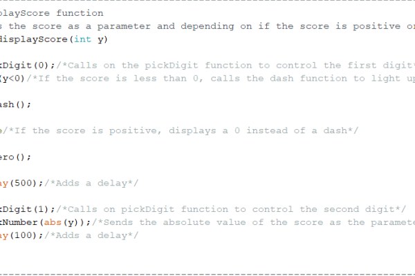
Now onto the last part of the project, the functions for the score. In the Loop function section, I mentioned a displayScore function. This is first function I will be explaining.
The function starts off by taking the score as its parameter. It then calls on the pickDigit function with a parameter of 0. This function lights up the specific digit that is gonna be changed. Since this function was called with a parameter of 0, that lights up the third digit from the left. Since that digit is now lit up, it can be changed. The next part of the function has an if statement that checks to see if the score is negative or not. If the score is negative, then the dash function is called upon, which lights up the negative sign on digit that was chosen earlier. If the score is not negative, it lights up a zero instead of a dash. A delay is added afterwards. Next, the pickDigit function is called upon again, now with a 1 as its parameter. Since its parameter is now one, the previous digit is turned off from being controlled and the first digit from the right is turned on.
Next, the pickNumber function is called upon with the absolute value of the score as the parameter. The pickNumber function takes the score as the parameter, and calls upon case with the corresponding number. Within each case is the corresponding function that lights up the number. For example, in case 1 is the function that lights up the number 1 on the display. Since the new digit was turned on, the pickNumber function lights up that digit depending on what the score is. If it is negative, the absolute value is sent so that the program understands. Finally, another delay is added, which completes all of the code for this project.
Source: LED Chaser Game
- How does the game determine when to award points?
Points are awarded if the pushbutton is pressed while one of the specific LEDs for the target color is currently on. - What controls the speed of the LED chaser?
A 10k ohm potentiometer connected to pin 8, pin 7, and pin 6 of the 555 timer allows you to change the speed. - Which Arduino pins are used for the pushbutton connection?
The pushbutton connects to Arduino Pin 2. - How are the colors assigned to specific LEDs in the code?
Red corresponds to LEDs 1, 4, and 7; yellow corresponds to LEDs 2 and 5; green corresponds to LEDs 3 and 6. - What happens if the score reaches 10 or -10?
An if statement at the end of the loop function resets the score once it reaches either 10 or -10. - How does the 555 timer interact with the decade counter?
Pin 3 output of the 555 timer connects to pin 14 clock of the decade counter to send pulses that light up the LEDs. - Why are resistors attached to the 7 segment display pins?
All resistors on the display pins are 560 Ohms and serve to reduce the voltage going into the pins. - How is the random color selected for the player?
The code sets the randColour variable to a random number from 1 to 3 to select red, yellow, or green.