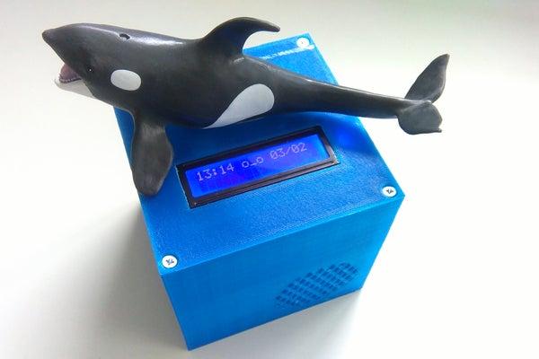
Summary of Kids MP3 Music Box
This article details a DIY Arduino-based MP3 player box designed for children, featuring RFID tag recognition to play specific audiobook folders. The project integrates 3D printing for the enclosure, wireless charging capabilities, and an LCD display for user interaction. The author outlines the assembly process, electronic connectivity, software features like alarm clocks and volume control, and provides a bash script for organizing audio files on the SD card.
Parts used in the Kids MP3 Music Box:
- LCD Display 1602 2x16 Big Characters 5 V
- RFID reader- NFC RFID-RC522 RF IC
- DFPlayer Mini MP3 Player Module
- 4 ohm 3Watts Loudspeaker
- Micro SD Card 8GB
- MPU6050 3 Axis Analog Gyroscope Sensor
- MINI USB NANO V3.0 Micro Controller Board
- DS3231 Precision RTC Alarmclock module
- JETech 3400 mAh Powerbank
- Universal DIY PCBA Qi Wireless Charger Receiver Module
- Prototype PCB Board Protoboard
- 2N 3904 Transistor NPN
- Resistors (1kOhm, 220Ohms)
When looking for some new DIY projects around arduino I found some nice ideas on RFID based MP3 players for Kids. And there is one great professional toy box on the market – these guys rule. They made a great business out of their smart idea. Check out – you’ll find their page!
As my two kids are getting into listening to audiobooks and music, more and more, and still are using good old compact discs with all the handling hassle, I decided to build such an MP3 player box with some nice features to make it a great individual toy for them. After I recently bought my first 3D printer this project seemed to be some good playground to also dive into 3D printing.
So I started into concept phase – which features would I want to implement – RFID, MP3 Player, WLAN (cancelled later), IMU control, LCD display, Alarmclock, wireless charging … Needed to do some research, what components I would need. Which components could I reuse? I still had an IMU, LCD module, some Arduino nanos.
With some experience in soldering and measuring the assembly is doable within 1-2 after work sessions.
The printing of the Box, consisting of a base, a cover plate and a charging station, takes some time (12+ hours depending on the printer and slicer settings), but I did that that during soldering.
Step 1: Components
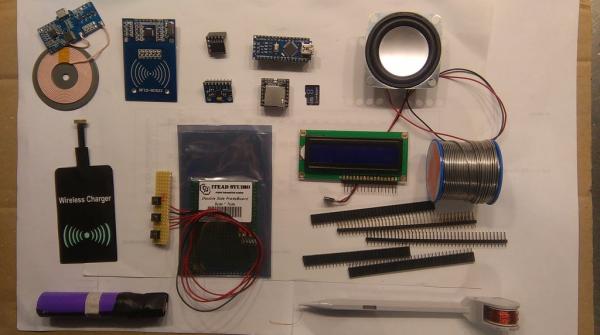
The components are really mainstream meanwhile. Here is a list of components I used for this project.
1. LCD Display 1602 2×16 Big Characters 5 V 122*44 MM blue
2. RFID reader- NFC RFID-RC522 RF IC
3. MP3 Player – DFPlayer Mini MP3 Player Module MP3 Voice Decode Board For Arduino Supporting TF Card U- Disk IO/Serial Port/AD
4. Loudspeaker- 4 ohm 3Watts 53MM Square Speaker 36MM External Magnetic Foam Edge Silvery Cap
5. Micro SD Card 8GB
6. MPU6050 3 Axis Analog Gyroscope Sensor
7. MINI USB NANO V3.0 CH340 5 V 16 Mt Atmega328 Micro Controller Board (nearly all pins used!)
8. DS3231 Precision RTC – Alarmclock module
9. Powerbank JETech 3400 mAh
10. Universal DIY PCBA Qi Wireless Charger Receiver Module – Blue + Black
11. Prototype PCB Board Protoboard Tinned Universal Breadboard Prototyping Solderless FR4 PCB Double-Sided 5×7 cm 50x70mm FR4
12. 1x 2N 3904: Transistor NPN TO-92 40V 0,2A 0,5W
13. 1x1kOhm resistor to limit base current, 3x220Ohms 0,5 w (parallel! to cater for wattage – one can use a higher spec resistor, I had these) for current load between emitter and collector. 2x1kOhms for TX and RX line between Arduino and DFplayer to kill noise – I did not have an issue here.
14. Some standard DIY electronics stuff – soldering iron, solder, clipper, connectors, cables…
14. A lot of energy and a couple of hours to assemble 🙂
Total price for above components ~30-35€ – mostly from aliexpress.com and dx.com. Shipping takes some time, but price is great.
Step 2: Electronics Connectivity
I did not draw a layout, nor did I use any handy tool like Fritzing or similar. Probably at a later point in time. Description below shows the connectivity. All pins that are not mentioned are not connected.
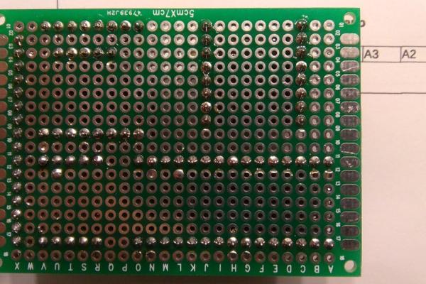
During soldering I kept measuring connectivity of the lines, end check with components mounted was also done. Nothing more annoying than having to look for one bad connection after all is assembled. Most care on GND and voltage +.
The pin layout of any component is available through google.
LC Display
LED—-GND
LED+—Via 220Ohm to 5V powerbank
DB7—Arduino D2
DB6—Arduino D3
DB5—Arduino D7
DB4—Arduino D8
E—Arduino A1/Pin 15
R/W—GND
RS—Arduino A0/Pin 14
V0— 10Kohm potentiometer Rx (to adjust contrast)
VDD—Powerbank +5V
VSS—GND
DFPlayer MP3 player
VCC—+5V Powerbank
RX— software serial Arduino D5 (potentially via 1kOhm resistor in case of noise problems)
TX— software serial Arduino D9 (potentially via 1kOhm resistor in case of noise problems)
SPK1—Speaker +
GND—Powerbank GND
SPK2—Speaker –
Busy—Arduino A7
GND—GND
NFC522 RFID reader
3.3V—Arduino 3.3V
GND—GND
MISO—Arduino D12
MOSI—Arduino D11
SCK—Arduino D13
SDA—Arduino D10
IMU 6050 gyro sensor
VCC—Arduino 3.3V
GND—GND Powerbank
SCL—Arduino A5/SCL
SDA—Arduino A4/SDA
ADO—+3.3V (High signal) for I2C address 0x69
DS3231 Real time clock
3,3V—Arduino 3.3V
SDA—Arduino A4/SDA
SCL—Arduino A5/SCL
GND—GND
Current load Trigger
2N3904 emitter — GND
2N3904 base — via 1kOhm to Arduino D6
2N3904 collector — via 3x220Ohms (parallel! – one can use a higher spec resistor, I had these) to +5V
Powerbank
V+ and GND lines of Powerbank connected through a female USB connector to power connector on board and connect to Vin/GND of Arduino). The powerbank is switched on via microswitch in the cover plate. I soldered a microswitch to V+ through a load resistor to GND to simulate a load state and switch it on. Thereafter the current load keeps it from switching off.
+5V — Power connector on board +5V
GND –Power connector on board GND
+5V of powerbank — load resistor — microswitch Pin A
GND — microswitch pin B
Step 3: Electronics Assembly
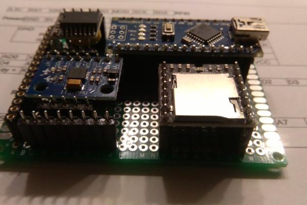
The board components – MP3 player, RTC, IMU, Arduino are mounted in sockets. Select and up/down keys, RFID, LCD and power are connected via self soldered ‘band cables’ long enough to fit into box later.
Microswitch to switch on powerbank is fixed coverplate – not shown in the pcitures.
I used a fixed power supply to test the setup.
While assembling I tested each component individually -> example Arduino sketches for the components are very helpful here.
As the powerbank had an auto-switch-off running with low current I included a transistor controlled load peak every 15 seconds for 100 ms via a 70 Ohm resistor (actually 3 parallel 220 Ohms to cater for sufficient wattage, it’s only a short peak but the three resistors will share the current and hence not be operated above specs).
Later it turned out that the Mini DFPlayer is pulling > 70mA continuously. As I used the powerbank auto-switch-off also for switching off of the box (by not triggering the current load anymore) I now need to re-think this.
Still having trouble with sleep mode of Arduino and DFplayer to drive down current – current does not drop below threshold to enable switch off. Feedback welcome.
Note: for the second Box I had to reorder another powerbank because I killed the electronics of my initial one. And look herer – this powerbank switches off 10 seconds after I stop triggering the load current -> switch off is working now.
The wireless charging receiver is plugged into the powerbank charging usb. The charger base is build into a charger box, printed with my 3D printer.
Step 4: Software
Software available on github
Programming is fun, I like to start with a quick nucleus of examples and to develop further. As I do not really do consequent specs, features planning and structured program plans I end up with some working but not really elegant code. This is always a todo -> go more into objects, separate in .h and .cpp …
However I do want to get the thing working quickly so in many cases I get there not on the most efficient path.
But the great thing is – as soon as the HW is working one can start doing all sorts of things.
I used the arduino IDE, a couple of libraries required – simply done with the arduino IDE library manager.
So my current version of the software supports:
Welcome message
Volume (duh)
Left/right tilt of box to switch to previous/next song and if RFID deactivated to next folder through back and forth.
Pause/Play (duh)
Initialize, learn new RFID – folder is assigned based on next RFID next SD card folder. Data is stored in Arduino EEPROM
Play folder assigned to RFID – assignment RFID-to-folder through learn function
Load and save parameters to enable settings saved. Factory reset 🙂
Clock and date setting.
Switch on/off alarm, setting alarm hour and minute, playing a fixed song for alarm.
Switch off RFID – play mp3 without it.
Some more ideas on my list – still to be implemented
Show temperature (the RTC can do that – it measures the temp to compensate impact to the quartz )
Start laughing when shaken,
Set song for alarm
Chose which folder is assigned to RFID in learn mode
Store folder assignment and last song played on RFID chip – reusability between boxes (I’m building another – two kids remember….?)
enable switch-off – this not working as of now without being connected to USB -> current load through Powerbank is reduced in this setting.
Info on folder structure on SD card
I had some mp3 audiobooks and music for my children stored. So I used some linux scripts to transform the songs to the right naming. Folders are to be named in sequence two-digit numbers (i.e. “00”, “01”, “02”…). Songs in there need to be named in sequence three digit numbers (i.e. “001.mp3”, “002.mp3”,…).
My switch-on-welcome mp3 (“Hello, I’m your toy box…”) is stored in folder “99” as “001.mp3”.
Script is not idiot proof and should be used only in a ‘copy’ directory and not on originals.
#!/bin/bash<br>let i=1
for file in *.mp3
do
 if (($i < 10)); then
	mv "$file" "00${i}.mp3"
 elif (($i < 100)); then
	mv "$file" "0${i}.mp3"
 else
	mv "$file" "${i}.mp3"
 fi
let i++
done
Source: Kids MP3 Music Box
- How do I organize MP3 files for the SD card?
Folders must be named with two-digit sequences (e.g., "00", "01") and songs within them must use three-digit sequences (e.g., "001.mp3"). - Can I assign specific music folders to RFID tags?
Yes, you can initialize and learn new RFID tags where the next folder on the SD card is assigned based on the scanned tag. - Does the device support playing music without an RFID tag?
Yes, there is a feature to switch off RFID functionality to play MP3s manually. - What controls allow navigation between songs or folders?
Tilting the box left or right switches to previous or next songs, and tilting back and forth moves to the next folder if RFID is deactivated. - How is the power supply managed to prevent auto-shutoff?
A transistor controlled load peak is triggered every 15 seconds to keep the powerbank from switching off due to low current draw. - Is it possible to set an alarm clock on this device?
Yes, the DS3231 module allows users to switch on/off the alarm and set the hour and minute for a fixed song to play. - What happens if the RFID learning function is used incorrectly?
Data regarding the RFID-to-folder assignment is stored in the Arduino EEPROM, allowing settings to be saved or reset to factory defaults. - Can the device display temperature information?
The RTC measures temperature to compensate for quartz impact, but displaying this value is currently listed as an idea to be implemented.