Summary of Keypad Input Processing: Basic Procedure and Applications
Summary: The article explains how matrix keypads work and how to connect and program 3x4 and 4x4 keypads with Arduino. It covers pinout discovery, reading key presses, displaying input on serial and LCD (including I2C), and using a keypad with a password to trigger a 5V relay. Example code and wiring guidance for various setups are provided.
Parts used in the Keypad Project:
- 4x4 matrix membrane keypad (or 3x4 keypad alternative)
- Arduino (Uno shown)
- LCD display (parallel or I2C-enabled)
- LiquidCrystal library
- Keypad library
- Wires/jumper cables
- LED and resistor (for pinout probing test)
- 5V relay (for password-activated switching)
- Power source (Arduino 5V)
Keypad Description
The Significance of Keypads as Input Devices and their Role in Various Applications
Keypads serve as essential input peripherals for data entry, similar to how keyboards are crucial to computers. Numerous applications heavily rely on users providing fundamental inputs, much like those available on the presented keypad.
A fundamental technique for reading input from a keypad involves a sequential process. Begin by creating a loop that establishes a connection between one of the rows and ground (for instance, row 1), and then proceed to read each column. In a scenario where column 4 registers a 0, the pressed key corresponds to ‘A.’ Otherwise, continue the process by connecting row 2 to ground and systematically reading the columns until the pressed key is successfully identified.”
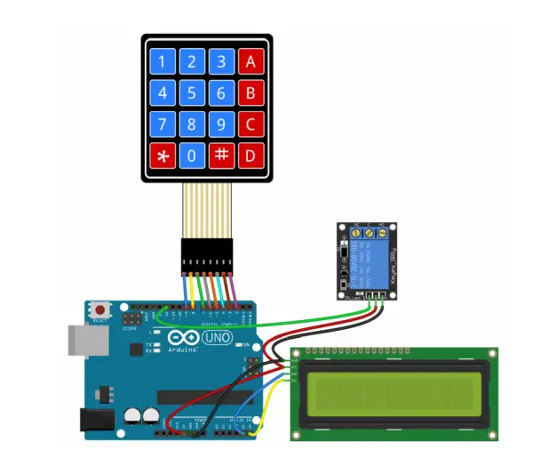
Circuit Test
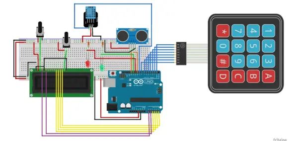
While the circuit features both the temperature and humidity sensor along with the ultrasonic sensor, the initial testing in this circuit is exclusively focused on assessing the functionality of the keypad and utilizing the LCD display for message visualization.
Modifications were necessary in the connections from previous scenarios due to the 4×4 keypad’s demand for eight digital pins. Consequently, the decision was made to employ the analog pins for interfacing with the LCD display.
Code
/* Arduino Security System with the Keypad and LCD
Simple one-digit password
*/
#include <LiquidCrystal.h> //include LCD library
#include <Keypad.h> //include keypad library
#define redLED 11 //define the LED pins
#define greenLED 12
const byte rows = 4; //number of the keypad rows
const byte cols = 4; // number of the keypad columns
char keyMap [rows] [cols] = { //define the symbols on the buttons of the keypad
{'1', '2', '3', 'A'},
{'4', '5', '6', 'B'},
{'7', '8', '9', 'C'},
{'*', '0', '#', 'D'}
};
char password ='6'; //create a password
byte rowPins [rows] = {1, 2, 3, 4}; // digital pins related to the row pins of the keypad
byte colPins [cols] = {5, 6, 7, 8}; // digital pins related to the column pins of the keypad
Keypad myKeypad = Keypad( makeKeymap(keyMap), rowPins, colPins, rows, cols);
LiquidCrystal lcd (A0, A1, A2, A3, A4, A5); // pins of the LCD. (RS, E, D4, D5, D6, D7)
void setup(){
lcd.begin(16, 2);
pinMode(redLED, OUTPUT); //set the LED as an output
pinMode(greenLED, OUTPUT);
setLocked (true); //state of the password
}
void loop(){
// char whichKey = myKeypad.getKey(); //define which key is pressed with getKey
lcd.setCursor(0, 0);
lcd.print(" Welcome");
lcd.setCursor(0, 1);
lcd.print(" Enter Password");
char whichKey = myKeypad.waitForKey(); //define which key is pressed with getKey
if(whichKey == '*' || whichKey == '#' || whichKey == 'A' || //define invalid keys
whichKey == 'B' || whichKey == 'C' || whichKey == 'D')
{
// location=0;
setLocked (true);
lcd.clear();
lcd.setCursor(0, 0);
lcd.print(" Invalid Key! ");
delay(1000);
lcd.clear();
}

if(whichKey == password )
{
setLocked (false);
lcd.clear();
lcd.setCursor(0, 0);
lcd.print(" Accepted ");
delay(1000);
lcd.clear();
lcd.setCursor(0, 0);
lcd.clear();
setLocked (true);
}
else
{
setLocked (true);
lcd.clear();
lcd.setCursor(0, 0);
lcd.print(" Try again ");
delay(1000);
lcd.clear();
lcd.setCursor(0, 0);
lcd.clear();
}
delay(200);
}
void setLocked(int locked){
if(locked){
digitalWrite(redLED, HIGH);
digitalWrite(greenLED, LOW);
}
else{
digitalWrite(redLED, LOW);
digitalWrite(greenLED, HIGH);

}

}
Keyboards are an effective means for users to engage with your project, enabling tasks like menu navigation, password input, and control over games and robots.
Within this guide, I’ll walk you through the process of configuring a keypad with Arduino. Initially, I’ll elucidate how Arduino identifies key presses, followed by a demonstration of how to ascertain the pin configuration of any given keypad. As a straightforward illustration, I’ll guide you through printing the recorded key presses on both the serial monitor and an LCD display. To culminate, I’ll demonstrate the activation of a 5V relay upon the successful entry of a designated password.
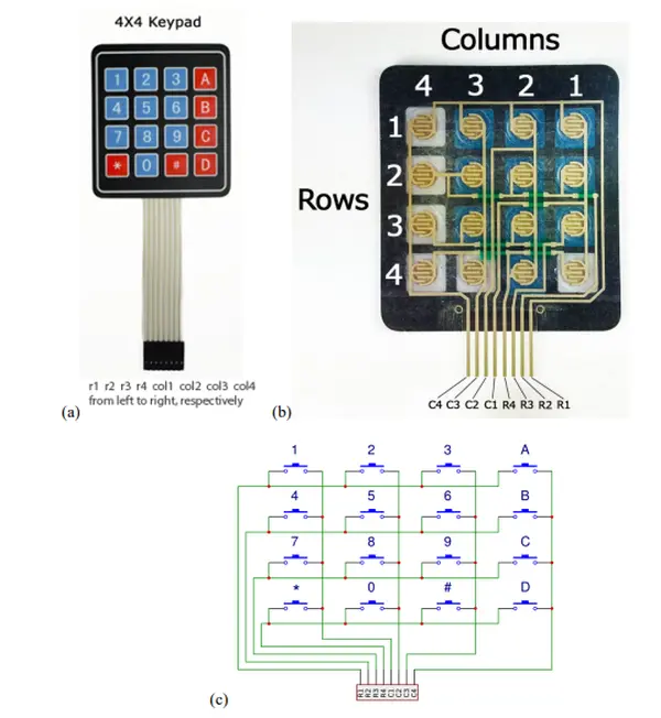
In this piece, I will employ a 4X4 matrix membrane keypad; however, I’ve also included code and wiring diagrams suitable for 3X4 matrix keypads. I have a preference for membrane-style keypads due to their slim profile and adhesive backing, allowing easy attachment to flat surfaces. Alternatively, telephone-style keypads with thicker buttons are available for those who favor that aesthetic. Moreover, even keypads sourced from repurposed old telephones can be effectively used with Arduino.
How Keypads Work
Keypad buttons are organized in rows and columns. A 3X4 keypad consists of 4 rows and 3 columns, while a 4X4 keypad comprises 4 rows and 4 columns.
Underlying each key lies a membrane switch. Within a row, each switch is linked to its counterparts through a conductive trace beneath the pad. Similarly, each switch within a column is interconnected – one side of the switch is electrically connected to all other switches in that particular column via a conductive trace. This arrangement results in each row and column being extended to a solitary pin, summing up to a total of 8 pins on a 4X4 keypad.
Depressing a button completes the circuit between a column and a row trace, thereby enabling the passage of current from a column pin to a row pin.
The schematic representation of a 4X4 keypad illustrates the interconnection between the rows and columns.
To ascertain the pressed button, the Arduino identifies the specific row and column pin engaged with the button. This process unfolds in four distinct stages:
1. Initially, with no buttons pressed, all column pins are maintained in a HIGH state, while all row pins are maintained in a LOW state:
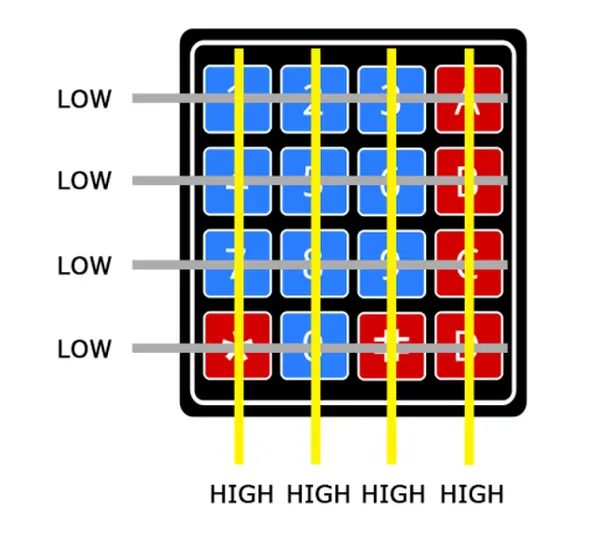
2. Upon button press, the column pin undergoes a transition to a LOW state due to the transfer of current from the HIGH column to the LOW row pin.
3. Having identified the column housing the pressed button, the Arduino’s task now lies in pinpointing the corresponding row. This involves systematically elevating each row pin to a HIGH state, simultaneously monitoring all column pins to identify the one that reverts to a HIGH state.
4. As the column pin regains a HIGH state, the Arduino successfully identifies the row pin linked to the depressed button:
As depicted in the provided diagram, the convergence of row 2 and column 2 uniquely signifies the activation of the number 5 button.
Connect the Keypad to the Arduino
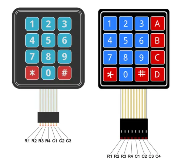
Refer to the accompanying diagrams to establish the connection between the keypad and an Arduino Uno. Select the appropriate diagram based on whether you possess a 3X4 or 4X4 keypad.
How to Find the Pinout of Your Keypad
In the event that the pin configuration of your keypad differs from the ones illustrated above, you can perform pin probing to ascertain the layout. To achieve this, construct a testing circuit by interconnecting an LED and a resistor for current regulation to the Arduino (or any available 5V power source), as demonstrated below:
Begin by identifying the keypad pins linked to the rows of buttons. Insert the ground (black) wire into the first leftmost pin. Depress any button in the first row and maintain pressure. Next, introduce the positive (red) wire into each of the remaining pins. If the LED illuminates at a particular pin, press and hold another button in the first row, then reinsert the positive wire into the other pins. If the LED lights up on a different pin, this signifies that the ground wire is connected to the pin corresponding to the first row. If no buttons in the first row trigger the LED, the ground wire is not linked to the first row. Progress to the next pin by shifting the ground wire, then press a button in another row, and iterate the aforementioned process until each row’s pin is determined.
To ascertain the pins connected to the columns, insert the ground wire into the pin associated with the known first row. Subsequently, press and hold a button in that row. Insert the positive wire into each remaining pin. The pin causing the LED to illuminate corresponds to the column linked to the button in question. Proceed to press another button in the same row, and for each column, repeat the process of inserting the positive wire to identify the pins associated with each column.
Programming the Keypad
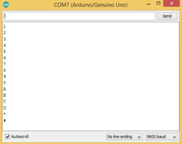
To provide a fundamental illustration of keypad setup, I’ll guide you through the process of printing each key press to the serial monitor.
The Code for a 4X4 Keypad
#include <Keypad.h>
const byte ROWS = 4;
const byte COLS = 4;
char hexaKeys[ROWS][COLS] = {
{'1', '2', '3', 'A'},
{'4', '5', '6', 'B'},
{'7', '8', '9', 'C'},
{'*', '0', '#', 'D'}
};
byte rowPins[ROWS] = {9, 8, 7, 6};
byte colPins[COLS] = {5, 4, 3, 2};
Keypad customKeypad = Keypad(makeKeymap(hexaKeys), rowPins, colPins, ROWS,
COLS);
void setup(){
Serial.begin(9600);
}

void loop(){
char customKey = customKeypad.getKey();

if (customKey){
Serial.println(customKey);
}
}
The Code for a 3X4 Keypad
Should you opt for a 3X4 keypad, you can utilize the following code:
#include <Keypad.h>
const byte ROWS = 4;
const byte COLS = 3;
char hexaKeys[ROWS][COLS] = {
{'1', '2', '3'},
{'4', '5', '6'},
{'7', '8', '9'},
{'*', '0', '#'}
};
byte rowPins[ROWS] = {9, 8, 7, 6};
byte colPins[COLS] = {5, 4, 3};
Keypad customKeypad = Keypad(makeKeymap(hexaKeys), rowPins, colPins, ROWS,
COLS);
void setup(){
Serial.begin(9600);
}

void loop(){
char customKey = customKeypad.getKey();

if (customKey){
Serial.println(customKey);
}
}
In the provided code, lines 3 and 4 establish the quantity of rows and columns attributed to the keypad.
Between lines 6 and 11, specific characters are assigned to individual buttons pressed on the keypad. This allocation mirrors the keypad’s physical arrangement. Should your keypad sport an alternative layout, you have the flexibility to specify the characters corresponding to each button press. For instance, if your keypad features a left-sided column of letters instead of the right, the adjustment would look as follows:
char hexaKeys[ROWS][COLS] = {
{'A', '1', '2', '3'},
{'B', '4', '5', '6'},
{'C', '7', '8', '9'},
{'D', '*', '0', '#'}
};
Once you’ve uploaded the code, access the serial monitor. Upon pressing a key, its corresponding value will be displayed.
Using an LCD with the Keypad
Now, let’s delve into the process of displaying key presses on an LCD. A 4X4 keypad utilizes 8 pins, while a 3X4 keypad uses 7 pins. Considering the substantial pin requirement, I’ll be utilizing an I2C-enabled LCD, which necessitates only 4 wires for connection to the Arduino.
Connect the Keypad and LCD
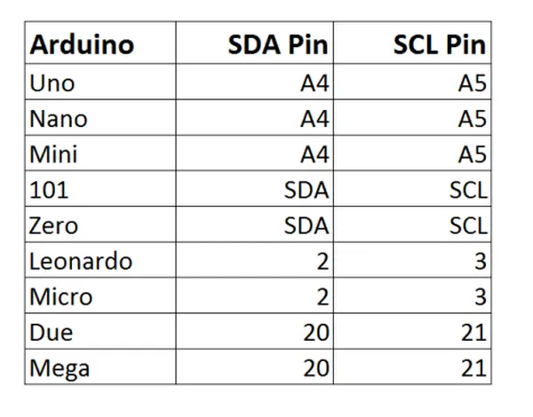
After the libraries have been successfully installed, proceed to link the LCD’s ground and Vcc pins to the Arduino. Following that, establish the connection of the LCD’s SDA and SCL pins as specified in the table below, tailored to the specific Arduino boards:
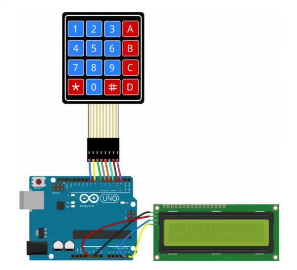
Next, establish the connection between the keypad and the Arduino. The setup should resemble the following configuration (illustrated here using an Arduino Uno):
Code for Output to an LCD
Once all the components are properly interconnected, proceed to upload the provided code to the Arduino:
#include <Wire.h>
#include <LiquidCrystal_I2C.h>
#include <Keypad.h>
const byte ROWS = 4;
const byte COLS = 4;
char hexaKeys[ROWS][COLS] = {
{'1', '2', '3', 'A'},
{'4', '5', '6', 'B'},
{'7', '8', '9', 'C'},
{'*', '0', '#', 'D'}
};
byte rowPins[ROWS] = {9, 8, 7, 6};
byte colPins[COLS] = {5, 4, 3, 2};
Keypad customKeypad = Keypad(makeKeymap(hexaKeys), rowPins, colPins, ROWS,
COLS);
LiquidCrystal_I2C lcd(0x21, 16, 2);
void setup(){
lcd.backlight();
lcd.init();
}
void loop(){
char customKey = customKeypad.getKey();
if (customKey){
lcd.clear();
lcd.setCursor(0, 0);
lcd.print(customKey);
}
}
On line 20, you will be required to incorporate the I2C address specific to your LCD:
LiquidCrystal_I2C lcd(0x21, 16, 2);
My LCD’s I2C address is 0x21; however, yours is likely to differ. Refer to the datasheet for your LCD to ascertain its designated I2C address.
Use a Password to Activate a Relay
A highly practical application of a keypad is employing it for secure keyed entry. You can establish a password and configure the Arduino to trigger a relay or another module solely when the correct password is input. The subsequent code snippet will prompt the activation of a 5V relay upon accurate password entry:
#include <Wire.h>
#include <LiquidCrystal_I2C.h>
#include <Keypad.h>
#define Password_Length 8
int signalPin = 12;
char Data[Password_Length];
char Master[Password_Length] = "123A456";
byte data_count = 0, master_count = 0;
bool Pass_is_good;
char customKey;
const byte ROWS = 4;
const byte COLS = 4;
char hexaKeys[ROWS][COLS] = {
{'1', '2', '3', 'A'},
{'4', '5', '6', 'B'},
{'7', '8', '9', 'C'},
{'*', '0', '#', 'D'}
};
byte rowPins[ROWS] = {9, 8, 7, 6};
byte colPins[COLS] = {5, 4, 3, 2};
Keypad customKeypad = Keypad(makeKeymap(hexaKeys), rowPins, colPins, ROWS,
COLS);
LiquidCrystal_I2C lcd(0x21, 16, 2);
void setup(){
lcd.init();
lcd.backlight();
pinMode(signalPin, OUTPUT);
}
void loop(){
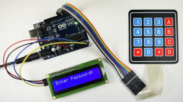
lcd.setCursor(0,0);
lcd.print("Enter Password:");
customKey = customKeypad.getKey();
if (customKey){
Data[data_count] = customKey;
lcd.setCursor(data_count,1);
lcd.print(Data[data_count]);
data_count++;
}
if(data_count == Password_Length-1){
lcd.clear();
if(!strcmp(Data, Master)){
lcd.print("Correct");
digitalWrite(signalPin, HIGH);
delay(5000);
digitalWrite(signalPin, LOW);
}
else{
lcd.print("Incorrect");
delay(1000);
}
lcd.clear();
clearData();
}
}
void clearData(){
while(data_count !=0){
Data[data_count--] = 0;
}
return;
}
Alterations to the password can be made on line 10 by substituting the “123A456” text with your personalized password:
char Master[Password_Length] = "123A456";
The password’s length must be defined on line 5:
#define Password_Length 8
In the provided example, the password appears to be 7 characters in length, but the actual length of the password is one greater than 7 due to the inclusion of a null character at the string’s end. To illustrate, if your password comprises 5 characters, you would input a value of 6 for the password length.
The designation of the output pin responsible for activating the relay is specified in line 7:
int signalPin = 12;
Upon successfully linking all components to the Arduino, your assembly should resemble the following configuration:
And there you have it. Setting up a keypad is relatively straightforward. With some experimentation, you should be able to adapt the provided code to suit the requirements of various projects that involve a keypad. Should you encounter any challenges, don’t hesitate to reach out in the comments section, and we’ll be glad to offer assistance.
- How does a matrix keypad detect which key is pressed?
By scanning rows and columns: columns are read for a LOW when a row is grounded, then rows are driven HIGH one at a time to identify the specific row that returns the column to HIGH. - Can I use a 4x4 keypad with limited Arduino digital pins?
Yes; the article shows using analog pins for other peripherals (like an LCD) when the keypad uses many digital pins. - What code is needed to print keypad presses to the serial monitor?
Use the Keypad library with makeKeymap, configure rowPins and colPins, call customKeypad.getKey(), and Serial.println the key when present (example code provided). - How do I find the pinout of an unknown keypad?
Use an LED and resistor: connect ground to a pin, press a row button, probe other pins with the positive wire until the LED lights to identify row and column pins. - Does the article show how to display keypad input on an LCD?
Yes; it provides example code using LiquidCrystal_I2C and explains connecting an I2C LCD to show pressed keys. - What is the best way to use a keypad for secure access?
Create a password stored in code and compare entered keys to the Master string; on match, activate a relay (example password-relay code provided). - How many pins does a 4x4 keypad require?
A 4x4 keypad uses 8 pins (4 rows and 4 columns). - How do I change the password in the example relay code?
Modify the Master string on the indicated line (char Master[Password_Length] = 123A456) and adjust Password_Length accordingly.