Summary of Keyfob Deadbolt using an Arduino Board
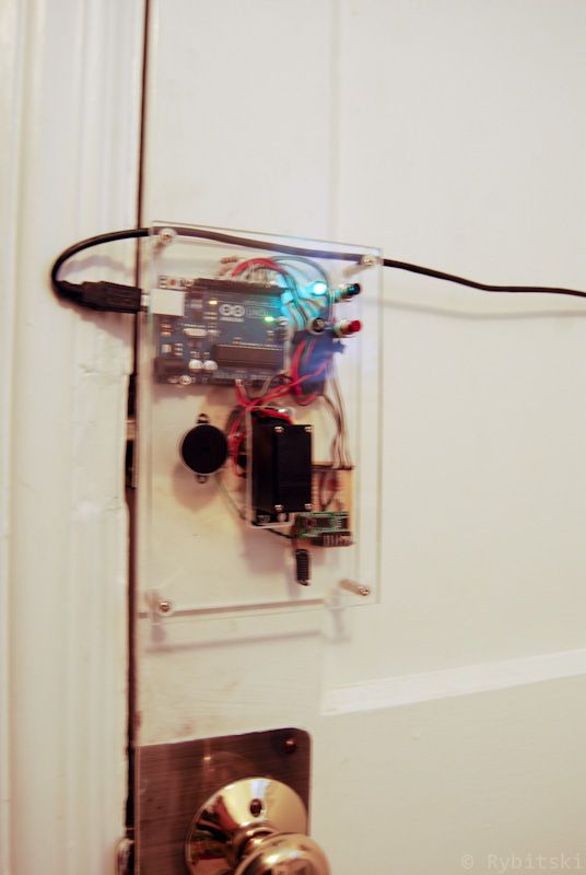
This article describes a DIY project to automate a deadbolt lock using an Arduino, eliminating the need for a physical key. The author mounts components on acrylic and uses a servo motor with epoxy putty to turn the bolt. A limit switch detects the lock's position, while push buttons and LEDs provide user feedback. The system is controlled via custom code that rotates the servo clockwise to lock and counter-clockwise to unlock.
Parts used in the Keyfob Deadbolt:
- Arduino Uno
- RF transmitter and receiver
- Servo
- 2 Push Button Switches
- Red LED
- Green LED
- Various Resistors
- piezoelectric speaker
- Perf Board
- Acrylic sheet
- Epoxy putty
The key to my apartment never worked quite right because it is a copy of a copy of a copy. I am fairly certain that the dead bolt is original to the building and the property manager seems to have lost the original key years ago. As a result unlocking the door was always a pain. Changing the lock wasn’t an option, but eliminating the need to use a key was.
Parts:
Arduino Uno
RF transmitter and receiver
Servo
2 Push Button Switches
Red LED
Green LED
Various Resistors
piezoelectric speaker
Perf Board
Step 1: Mounting Parts
used a couple of pieces of acrylic that I acquired in the dumpster of the plastic shop next to my place of work (they throw out alot of small pieces like this). Alternatively another material could be used if you don’t have access to acrylic, but it is easy to work with and looks cool.
Using a piece of paper trace the mounting holes for your dead bolt and transfer them onto your acrylic sheet. Since most dead bolts are going to be slightly different I am not sharing the template I made out of a piece of paper (mainly because it isn’t anything worth sharing).
Leave the paper covering on while working with the acrylic. The paper makes it easy to mark where to cut/drill as well as protects the material from scratches. Once all of your cuts are made and your holes are drilled you can start installing components such as LEDs and switches.
Step 2: Servo
I used an old parallax servo I had in my parts bin. This small servo is more than strong enough to turn the deadbolt. In order to attach the servo to the lock shaft I used epoxy putty. Epoxy putty is very easy to use and is extremely versatile. The wire you see sticking out of the putty will be used as the arm for the limit switch.
At some point the wires to my servo had been cut so I had to open the case and solder on new ones. I took that opportunity to solder on a second wire to the 5v line and connected it to the limit switch arm.
Step 3: Wiring
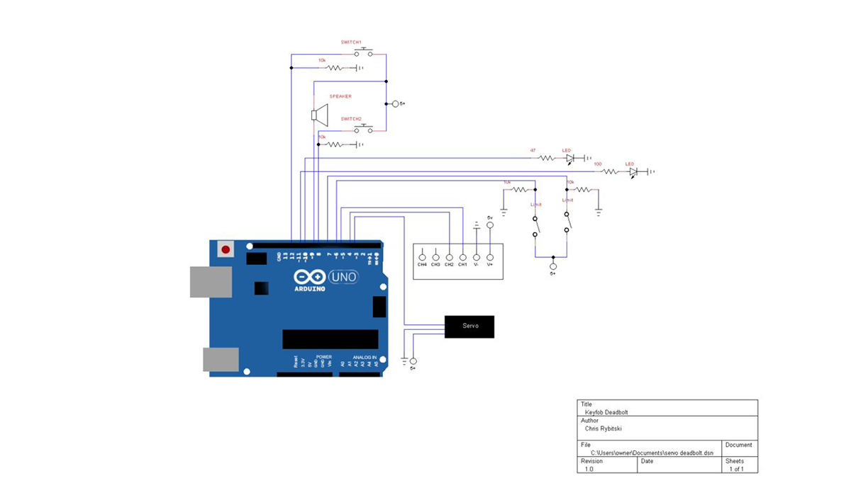
Screws were countersunk from the back of the acrylic. A wire was attached to each screw and then to a digital pin on the Arduino. When the wiper with the 5v wire touches the screw it pulls the digital pin high on the Arduino. Please see the schematic for further details.
Step 4: Program
//1700 CCW; 1500 Stop; 1300 CW
//written by Chris Rybitski
#include <Servo.h>
RF transmitter and receiver
Servo
2 Push Button Switches
Red LED
Green LED
Various Resistors
piezoelectric speaker
Perf Board
- Why did the author change the lock mechanism?
The original key was a poor copy of a copy, and the property manager lost the original key years ago. - What material was used for mounting the parts?
The author used pieces of acrylic acquired from a plastic shop dumpster. - How was the servo attached to the lock shaft?
Epoxy putty was used to attach the servo to the lock shaft. - What determines if the servo locks or unlocks the door?
The program turns the servo clockwise to lock and counter-clockwise to unlock. - How does the system detect the lock's position?
A limit switch arm connected to a 5v wire touches a screw to pull a digital pin high on the Arduino. - Can the code be improved by the user?
Yes, the author states the code may not be efficient and invites users to improve it. - What happens when the wiper touches the screw?
It pulls the digital pin high on the Arduino. - Is the template for drilling holes shared?
No, the author does not share the paper template because most dead bolts are slightly different.