Summary of Key Safe
Summary: A DIY Arduino-based keypad key safe lets family members leave keys securely inside a locked box. It uses a Matrix 4x4 keypad, LCD display, and SG90 servo to lock/unlock with a user-set passcode. The LCD shows Get Some Food to remind whether someone will return for dinner. Controls: * clears input, # checks the passcode; correct code moves servo to open, wrong code prompts retry. Wiring notes, power, and soldering tips are included.
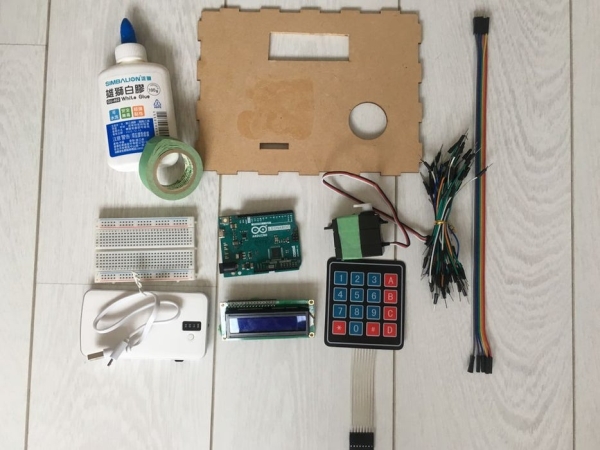
Parts used in the Key Safe:
- Arduino Leonardo
- Matrix Keypad 4x4
- LCD 16x2
- Micro Arduino Servo Motor SG90
- Jumper Wires Male to Female
- Jumper Wires Male to Male
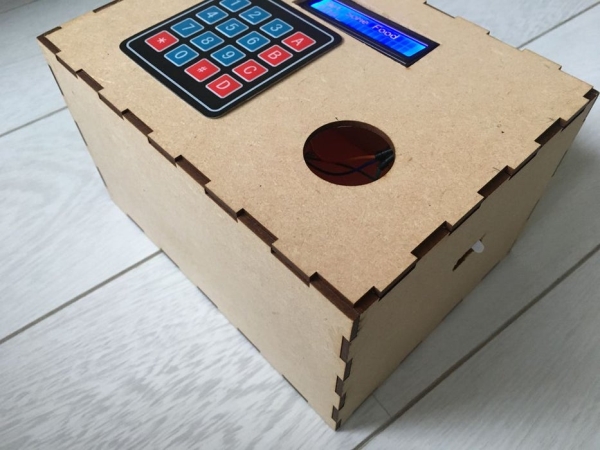
- Laser Cut 3D Printed Case (15x20x12cm)
- Tape or Clay
- Wood Glue
- Charger
- Breadboard
- Welding Gun (soldering iron) and solder
During weekdays, I seldom bring my key out, but this causes difficulty when my mother left the house. By having no other choices, my mom has to leave the key inside the cabinet beside the door, which has no guarantee of whether the key is safe or not. By having this key lock, the one who is leaving the house can left the key inside this box to prevent others from stealing the key without any protection. Inasmuch as my mom will either be home before dinner or after dinner, I will need to know whether I need to find something to eat or not. This is the reason why the lock prints “Get Some Food”.
Step 1: Prepare the Materials
Arduino Leonardo (Arduino)
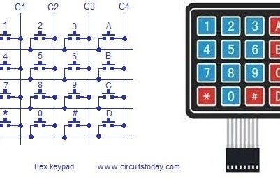
Matrix Keypad 4×4 (Amazon)
LCD 16×2 (Amazon)
Micro Arduino Servo Motor SG90 (Amazon)
Jumper Wires Male to Female (Amazon)
Jumper Wires Male to Male (Amazon)
Laser Cut 3D Printed Case x1 (15x20x12cm)
Tape / Clay
Wood Glue
Charger
Breadboard / Welding Gun
Step 2: Code
1. Download 4 system from the library.
2. Make sure to declare the servo pin as 4 (any number except 2 or 3: both of them will not work if LCD occupies SDA and SCL).
3. Different rows and columns belong to different pins, so make sure to declare the correct one.
4. Set up own passcode for the lock.
5. “resetLocker” means when the system turns back to origin: LCD prints “Get Some Food” and “Pin”, and the servo turns to 40 degrees, which locks the box (the degree depends on different servo or the position of the servo).
6. “unlockdoor” works if the user enters the correct password, making the servo to turn to 110 degree (open) and the LCD print “pass”. In the other hand, the LCD will print “Wrong! Try Again” if the passcode is incorrect.
7. By pressing “*”, users can clear the password they entered; by pressing “#”, the machine can check for the passcode.
Step 3: The Circuit
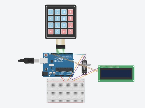
1. Plug in all the wires in the pins declared for the coding part.
2. Be aware of the positive and negative electrode or else the components might break (positive electrode: 5V, negative electrode: GND).
3. If the breadboard occupies a large space, use a welding gun solder to connect the wires together. In order to let the circuit operate, make sure the wires are not burned out, and the solder surrounds the wires (Tips for welding: Use the welding gun to heat the wires, put in the solder to let it melt until the liquid surrounds the wires, then remove the welding gun and the solder).
4. Using a breadboard: pin 6-13 should be the keypad, pin 4 is for servo, LCD’s SCL and SDA connect to the two pins on the left. The positive and negative electrode of both servo and LCD should be in the positive and negative part of the breadboard, then use two other wires to connect the holes of the breadboard to 5V and GND.
5. Using a welding gun: pin 6-13 should be the keypad, pin 4 is for servo, LCD’s SCL and SDA connect to the two pins on the left. The negative electrode of both the servo and LCD should be in the two holes of GND, but there is only one 5V hole, which means the positive electrode of both the servo and LCD should be together using soldering and them connect both of the wires to the 5V wire.
Read more: Key Safe
- What is the purpose of this key lock?
To let someone leaving the house leave a key inside a locked box so others cannot steal it. - Which Arduino is used in the project?
Arduino Leonardo is used in the project. - How does the system indicate whether to get food?
The LCD prints Get Some Food when the system is reset to its origin state. - Which pin should the servo be declared on?
The servo pin should be declared as pin 4; avoid pins 2 or 3 if LCD uses SDA and SCL. - How do users clear entered input or submit the code?
Pressing * clears the entered password and pressing # checks the passcode. - What happens when the correct passcode is entered?
The unlockdoor function turns the servo to 110 degrees and the LCD prints pass. - What happens when an incorrect passcode is entered?
The LCD prints Wrong! Try Again. - How should power and ground be handled on the breadboard?
Place servo and LCD positive to 5V and negative to GND on the breadboard, then link the breadboard rails to the Arduino 5V and GND.