Purpose and description of this guide
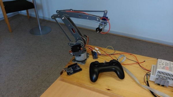
This instructable is a hand-in for a school project that we made. The purpose of this project was to create a robot arm control using thumbsticks. We had to use an Arduino Uno for the control and in addition, we had to implement some sort of actuator or sensor in the setup. We modified a Logitech gamepad using the two thumbsticks. Two push buttons where available to use, but only one activates the magnet (on L3), and the button on R3 is unused. Our school had a robot arm, a Logitech gamepad controller, an electromagnet and two thumbsticks made available to us.
Step 1: Components List
– Arduino UNO R3
– Bredboard
[http://www.ebay.com/itm/1PCS-Mini-Prototype-Solderless-Breadboard-400-Contacts-For-arduino-Raspberry-pi-/151909047511?hash=item235e7c1cd7:g:6AMAAOSw7FRWZlbJ]– 2 x Thumbsticks (with push buttons)
[http://www.ebay.com/itm/2x-3D-Controller-Joystick-Sensor-Module-Replacement-ThumbStick-for-Xbox-One-/301845670210?hash=item4647676942:g:35sAAOSwT~9WlFx7]– 5v Electromagnet
[http://www.ebay.com/itm/DC-5V-0-8A-Electric-Lifting-Magnet-11LB-5Kg-Holding-Electromagnet-Lift-Solenoid-/201262661479?hash=item2edc307f67:g:MhUAAOSwT6pVg4Sv]– 5v DC Power Supply
[http://www.ebay.com/itm/New-DC5V-3-8A-20W-Universal-Regulated-Switching-Power-Supply-Adapter-AC-100-265V-/121524932692?hash=item1c4b735054:g:i1AAAOSwyZ5UmDXQ]– DIY 4-Axis Servos Control Palletizing Robot Arm Model
[http://www.ebay.com/itm/DIY-4-Axis-Servos-Control-Palletizing-Robot-Arm-Model-for-Arduino-UNO-MEGA2560-/351150915118?hash=item51c239be2e:g:5TgAAOSwVFlT9D5H]– Logitech Precision Gamepad
[http://www.ebay.com/itm/Logitech-Precision-Pc-Controller-Game-pad-/172201040957?hash=item2817fb5c3d:g:TMEAAOSwYmZXMd9n]– 2x 10K Ohm resistors
[http://www.ebay.com/itm/10K-Ohm-0-25w-Carbon-Resistors-1-4w-Resistor-10-20-or-50-Per-Pack-UK-Seller-/172097237753?var=&hash=item2811cb72f9:m:mU93P7fRSLcp2Eltt2Ud3Rg]– PCB board with solder pads
[http://www.ebay.com/itm/10pcs-70mm-x-90mm-Welding-Soldering-Prototype-Copper-PCB-Printed-Circuit-Board-/121536843744?hash=item1c4c290fe0:g:D0cAAOxy69JTFw2i]– Jumper wires (in various lengths)
[http://www.ebay.com/itm/65pcs-Solderless-Flexible-Breadboard-Jump-Cable-Wires-Male-to-Male-for-Arduino-/281544756865?hash=item418d600e81:g:NRUAAOSw7ThUkDmO]Step 2: Modifying Gamepad Controller
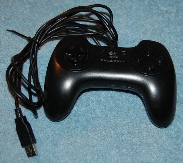
This is what the gamepad looked like before modification. Since we decided that thumbsticks where the way to go, we had to cut away and replace the gut of the gamepad [First picture].
We modified the gamepad, so it had to thumbsticks instead of a d-pad and command buttons. We soldered the thumbsticks on a PCB board and wired them. Two 10K Ohm resistors where also soldered to the push buttons of the thumbsticks [2nd – 5th picture].
We made two large holes on the front panel, so the two thumbsticks would fit in [Last picture].
Step 3: Wiring Diagram
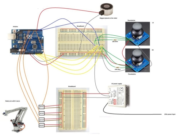
For full details open picture in full screen.
Step 4: Arduino Code
#include  <Servo.h>
// Create servo objects
Servo servo1;
Servo servo2;
Servo servo3;
Servo servo4;// Create names to the analog input pins
int pin0 = A0;
int pin1 = A1;
int pin2 = A2;
int pin3 = A3;// Setup of angle variables we have to use further down in the program
int angle1;
int angle2;
int angle3;
int angle4;// Setup of value variables we have to use further down in the program
int value1;
int value2;
int value3;
int value4;// Setup of limit values
long int forservo1 = 20000;
long int forservo2 = 20000;
long int forservo3 = 20000;
long int forservo4 = 20000;void setup()
{
  pinMode(3, INPUT); /* Use button on thumbstick to set pin 3 as input */
  pinMode(4, OUTPUT); /* Set pin 4 as output to the magnet */  // Attaches the servo on pins to the servo objects
  servo1.attach(5);
  servo2.attach(6);
  servo3.attach(9);
  servo4.attach(10);
}

void loop()
{
  // read analog values from joysticks
  value1 = analogRead(pin0);
  value2 = analogRead(pin1);
  value3 = analogRead(pin2);
  value4 = analogRead(pin3);

  // 10 bit value is too big, so we change the scale from 0 - 1023 proportionately to 1 - 29
  value1 = map(value1, 0, 1023, 1, 29);
  value2 = map(value2, 0, 1023, 1, 29);
  value3 = map(value3, 0, 1023, 1, 29);
  value4 = map(value4, 0, 1023, 1, 29);

  // it needs correction of positions, because joysticks are not very precise to stay exactly in the center
  if(value1  <= 17 && value1 >= 13) // if value1 if between 13-17, then it's equal to 15 */
      value1 = 15;
  if(value2  <= 17 && value2 >= 13)
      value2 = 15;
  if(value3  <= 17 && value3 >= 13)
      value3 = 15;
  if(value4  <= 17 && value4 >= 13)
      value4 = 15;

  // Change initial value 'forservo' which is used to turn servo slower. This value has got very big scale.
  // We add or substract (depends on turning direction) difference between analog value and center from 'forservo'
  forservo1 = forservo1 - (value1 - 15);
  forservo2 = forservo2 - (value2 - 15);
  forservo3 = forservo3 + (value3 - 15);
  forservo4 = forservo4 + (value4 - 15);

  // this part do not let variables 'forservo' go out of the limits
  if(forservo1  < 1) // if forservo1 is less than 1, then it's equal to 1
      forservo1 = 1;
  if(forservo1  > 20000) // if forservo1 is greater than 20000, then it's equal to 20000
      forservo1 = 20000;
  if(forservo2  < 1)
      forservo2 = 1;
  if(forservo2  > 20000)
      forservo2 = 20000;
  if(forservo3  < 1)
      forservo3 = 1;
  if(forservo3  > 20000)
      forservo3 = 20000;
  if(forservo4  < 1)
      forservo4 = 1;
  if(forservo4  > 20000)
      forservo4 = 20000;

  // change used value to angle of servo. Angles are adjusted during testing
  angle1 = map(forservo1, 1, 20000, 10, 180);
  angle2 = map(forservo2, 1, 20000, 10, 180);
  angle3 = map(forservo3, 1, 20000, 10, 180);
  angle4 = map(forservo4, 1, 20000, 10, 180);

  // send angles to servos
  servo1.write(angle1);
  servo2.write(angle2);
  servo3.write(angle3);
  servo4.write(angle4);  // activates the magnet
  while (digitalRead(3) == HIGH) { /* Read pin 3 from the thumbstick */
  digitalWrite(4, HIGH); /* Write to pin 4 (magnet) */
  }}
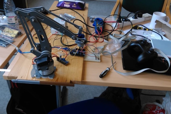
Step 5: Testing (pictures)
Step 6: Result (video)
Source: Joystick Controlled Robot Arm Using an Arduino