Summary of IoT: Weather Box (with Custom Alarms & Timers)
This article details the construction of an IoT-based Weather Box using a NodeMCU microcontroller. The device displays local weather data fetched via an API, monitors room temperature with a DHT11 sensor, and features custom alarms and timers. It utilizes an MQTT server (Cayenne) to upload sensor data for remote viewing. The project includes designing a wooden enclosure, wiring components like an LCD screen and buzzer, and writing extensive Arduino code to manage multiple functions through a button interface.
Parts used in the Weather Box:
- nodeMCU 0.9
- LCD screen 16x2
- Push buttons - 3
- DHT11 temperature sensor
- Buzzer or beeper
- Mini breadboards
- Jumper wires
- 1000 Ω resistor - 3
- Small wooden box
- Plywood 0.5mm
- Fevicol glue
- Jewelry box hinges
- Narrow ice cream stick
- Double sided tape
Please vote for me in the contests i have entered. Hope you enjoy the instructable, and happy making.
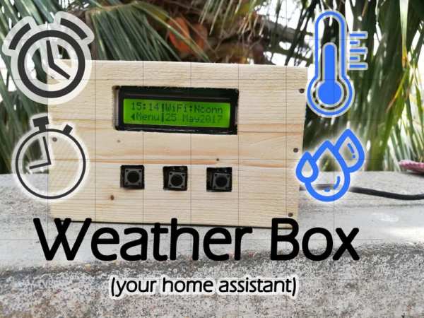
I was, some time ago, quite interested in IoT projects and so I thought it would be fun to make something associated with the Internet. I recently purchased the micro-controller called the nodeMCU and it’s superb. After having decided to build a weather station that would display all the weather information with just a push of a button, I delved into the first step of making it. But, there is something that remains to be added. That is, it’s not just confined to doing simply that much(displaying the weather information of my city), but also it is able to keep your alarms and timers for you. Doesn’t that sound cool?!
That means it’s like an Alarm clock with custom timers combined with a Weather station. It also does a fair job of displaying the time and date. It works with the nodeMCU and quite a few other components included in the build. Still, it could be exposed suitably for more improvement like the addition of more features.
I have also used a DHT11 temperature sensor for measuring the room’s temperature in which this weather box of ours may be in, besides fetching information from the internet about the weather. So that you can have a good comparison between the both. I also decided to use an MQTT server for uploading this information on the web so that i can, from anywhere, have a look at the local weather information sensed by this prototype. I guess that will suffice the introduction part.
Step 1: What Do You Need?
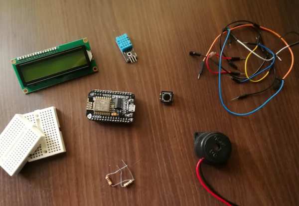
So now, I guess, it’s time for us to heap all the needful things on the desk and get started.
Things we need:
- nodeMCU (Micro-controller, I am using the 0.9 version)
- LCD screen – 16×2
- Push buttons – 3
- DHT11 temperature sensor
- Buzzer or beeper
- Mini breadboards
- Jumper wires
- 1000 Ω resistor – 3
- And a small wooden box to assemble all the things inside.
And that’s all you need.
Step 2: What the BOX About the Weather Box?
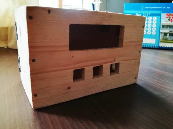
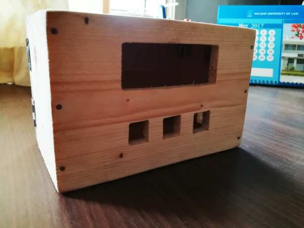
I used a software called ‘SketchUp’ to design a basic and a small box for enclosing all the stuff in so that it looks compact and stays sturdy. Well, all the dimensions are given in the SketchUp photos, and it’s not really difficult for any carpenter to make. It’s just a few hours’ job. I had a local carpenter friend make it, and he quite eased my job a lot. So thanks to him.
The material I used was 0.5mm plywood, and Fevicol to stick all the walls together. Also, I had a couple of jewelry box hinges so I thought, why not put them to use now?
And that’s how I made the box. I had certainly tried to get this project done in a medium sized plastic container but it was too flimsy and difficult to maintain. You could see a picture of it above.
And now it looks much better.
Step 3: Pin Allotment and Planning
Alright, so let’s talk about how I had to distribute the pins among all the components.
The LCD screen
The LCD, as we all would know, needs at least 6 I/O pins to interface it with the microcontroller. They may be given as follows: enable, register select, D04, D05, D06, D07.
Enable – digital I/O pin 0
Register select – digital I/O pin 1
D04 – digital I/O pin 2
D05 – digital I/O pin 3
D06 – digital I/O pin 4
D07 – digital I/O pin 5
There are three push buttons which we will be using, so obviously we would need three digital I/O pins,
LeftButton – digital I/O pin 6
CenterButton – digital I/O pin 7
RightButton – digital I/O pin 8
The buzzer
The can be connected to the digital I/O pin 9.
The DHT11 temperature sensor
This sensor has one output pin and will go to the digital I/O pin 10
And that are all the pins we will be using.
Step 4: The Assembly
Now if you’ve done making the box and are replenished with everything you need, then it’s time to assemble everything inside that box.
- I guess we need to start with the push buttons. I used a narrow ice cream stick to make a base for the push buttons. Maybe the photos will give a better understanding.
- Then I took the nodeMCU and the bread boards and stuck them onto the base of the box with double sided tape.
- I then connected the push buttons to the appropriate digital I/O pins.
- Thirdly, I had the LCD screen plunge through it’s cutting and then gripped it well to the box with some tape from the inside. Now it stands well I guess.
- Then I began making the connections for the LCD screen. In case you do not know how to do it, then you could use a photo which I will provide as a guide.
- I then attached the buzzer or the beeper on the inside of the box with double sided tape and connected it’s positive terminal to the digital pin 9
- The DHT11 sensor has three terminal pins: 5v, gnd, and output. Therefore the output pin will go to the digital pin 10 of the nodeMCU and 5v and ground are obvious where to go.
- Also to add, DHT11 is the only thing that will stay outside the box to sense the temperature outside. You could see in the photos.
And I guess, that’s all about the assembly and it took me about two hours to assemble everything inside without it being precarious.
Step 5: Vitals of the Code

The code is about 450 lines in length. Now, my code certainly does use some important libraries which you will be needing to download. I will provide you the link as we proceed. Make sure you have the Arduino IDE installed on your computer. Also, make sure you have the esp8266 boards installed too. If you haven’t, click here.
Alright. The first thing or the very first step we do before we code, is to understand the functionality of our device and code accordingly.
- So our WB(weather box) could access the internet and retrieve the appropriate weather information through an API call.
- It could also sense the temperature of the environment it’s in with a sensor of it’s own and send it to an MQTT broker.
- It could also keep alarms and timers for you.
- It is also capable of display time and date.
That means we need to integrate all these functions under one caption or code. That’s challenging and I’ve done that.
What are the libraries that we need?
- LiquidCrystal library. Since we are using an LCD as the chief interface between you and the WB, this library is indispensable. To our ease, this library, by default, is an inbuilt library in the Arduino IDE.
- ESP8266WiFi library. This library allows your ESP8266 to connect to the Wifi and access the internet. This library comes in a package you would’ve downloaded while installing the ESP8266 boards in the board manager.
- ArduinoJson library. When calling the API, the data you will receive will be in JSON(JavaScript Object Notation) format. So if you want to convert it to a usable format, you need to parse it. And the ArduinoJson library does it for us. We must credit the makers of such libraries with praise for making our lives so much easier.
- Library for the DHT11 sensor.
- Timelibrary. For keeping our time. The library functions are listed here.
- TimeAlarms library. Used to for us to set alarms and timers. The library functions are listed here.
The last two libraries are supposed to be used together. You could use the time library independently but not the TimeAlarms library.
So after having downloaded the libraries, we will begin coding.
<strong><em>Do you like to code? Comment below.</em></strong>
Step 6: The API Call

The most important thing there is to an API call is the API key. I am connecting to the website, openweathermap.org to get all the weather information.
So you need to follow the procedure to open an account over there and get an API key and it’s absolutely free.
To call the API key,
- The first step is to connect to the server.
- Secondly, you need to use your API key in the URL.
- Then you need to use the GET method to retrieve the data from that URL.
To make the available data in a usable format,
- You need to then store the available data in a string.
- The data you receive will be in JSON format. So you need to parse it.
- And then, you will store the desired information in some global variables so that you can use them anywhere in the code.
The following is a code sample, which i typed to demonstrate to you how it works.
This part basically declares the libraries used, creates the variables and objects for the library to refer.
<p>#include <ArduinoJson.h><br>#include  <ESP8266WiFi.h></p><p><br>String result; //the string in which the data will be stored after the API call</p><p>char servername[]="api.openweathermap.org"; //server name
String APIKEY = "YOUR_API_KEY"; //the API key
String CityID = "1264527"; //your city ID</p><p>//Assigning your global variables to store the received weather information</p><p>String Description;</p><p>String Place;</p><p>float Temperature;
float Humidity;
float w;</p><p>WiFiClient client; </p>
Basic setup code.
<p>void setup() {<br>  // put your setup code here, to run once:
  Serial.begin(9600);
  WiFi.begin("your ssid", "your password"); //begins wifi connection
  while(WiFi.status() != WL_CONNECTED){ //waits until connection has been established
    Serial.print(".");
    delay(500);
  }
  Serial.println("Connected!");
  Serial.println(WiFi.localIP()); //prints the IP address
}</p>
Code to create a function that gets data.
<p>void weatherData(){<br>    if (client.connect(servername, 80)) {  //starts client connection, checks for connection
    client.println("GET /data/2.5/weather?id="+CityID+"&units=metric&APPID="+APIKEY); //calls the api using the get method before the URL. Note: The URL uses the api key.
    Serial.println("Server is accessable");
    client.println();
  }
  else { // if server is not available
    Serial.println("connection failed"); //error message if no client connect
    Serial.println();
  }
  result = ""; //makes the string void of any data stored previously to store new data
  while (client.available()) { //connected or data available
    char c = client.read(); //gets byte from ethernet buffer
      result = result+c;
    }
  Serial.println(result);
  result.replace("[", " "); //I am facing an error. Just to avoid it, i have to type this
  result.replace("]", " "); //and this too.
  client.stop(); //stop client
  Serial.println("Recieved");</p><p>  //parses the string called result</p><p>  StaticJsonBuffer<1024> jbuff; </p><p>  JsonObject &root = jbuff.parseObject(result);
  if (!root.success())
  {
    Serial.println("parseObject() failed");
  }</p><p>  //stores all the desired info in temporary variables.
  String location = root["name"];
  float temperature = root["main"]["temp"];
  float humidity = root["main"]["humidity"];
  String description = root["weather"]["description"];
  float wind = root["wind"]["speed"];</p><p>  //transfers all the info from the temporary variables to global variables which you can access anywhere in the code.
  Place = location;
  Temperature = temperature;
  Humidity = humidity;
  w = wind * 3.6;
  Description = description;
}</p>
The loop function to display all that you want to on the serial monitor.
<p>void loop() {<br>    weatherData(); //calls the function which we discussed above
    Serial.println(Temperature);
    Serial.println(Place);
    Serial.print("H: ");
    Serial.println(Humidity);
    Serial.print(w);
    Serial.println(" kmph");
    Serial.println(Description);
    delay(8000); //delays for 8 seconds
}</p>
So, that’s a basic example of an API call and parsing JSON data. If you’re done, let’s step further!
Step 7: MQTT Client and Broker
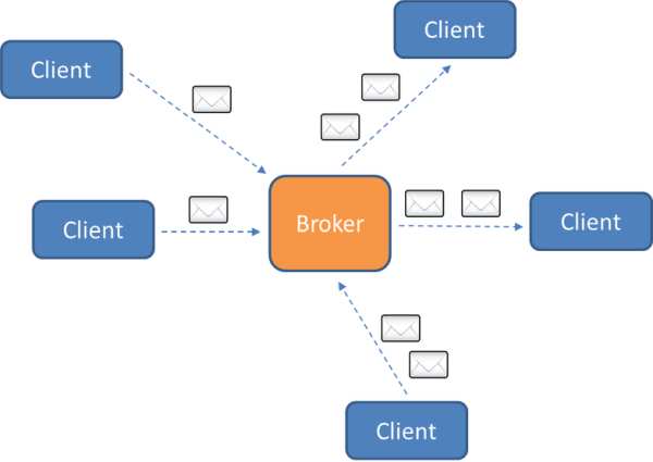
\As I have said before, we will be uploading our sensor data to an MQTT broker on the internet so that we can view it from anywhere. For me, the Cayenne dashboard is the most convenient so i decided to use it.
- First, you must create an account.
- After creating an account, click on ‘Add New’.
- Then click on ‘Device/Widget’
- Click on ‘Bring your own thing’, which is at the bottom.
- A new page will appear indicating your MQTT username, password, and the client ID which are unique for you. These will be implemented in the code to identify your device.
The following is a code sample for you to understand how MQTT protocol. We will also be using the Cayenne-MQTT-ESP8266 library to make things much easier for us.
<#include <CayenneMQTTESP8266.h>

char ssid[] = "ssid";
char wifiPassword[] = "wifiPassword";

char username[] = "MQTT_USERNAME";

char password[] = "MQTT_PASSWORD";
char clientID[] = "CLIENT_ID";

void setup() {

  Serial.begin(9600);
  Cayenne.begin(username, password, clientID, ssid, wifiPassword);
}

void loop() {

 Cayenne.loop(); //this function must be called regularly to keep the connection stable
  float sensorInfo = analogRead(A0);
  Cayenne.virtualWrite(0, sensorInfo); //virtualWrite(channel, data) is function with two parameters. Channel - you want to send the data to and second parameter is the data itself.
}
- After your board has been connected to Cayenne you will be automatically directed to the dashboard where you can use the available custom widgets.
- Make sure you specify the channel properly and correspond to that channel to send data in your code.
- After you’ve done about that, create a new project and drag and drop widgets as you like from your devices.
After that, you will be able to send and receive data smoothly. For my purpose, I used only two widgets icon namely ‘temperature’ and ‘humidity’.
Step 8: Structure of the Code
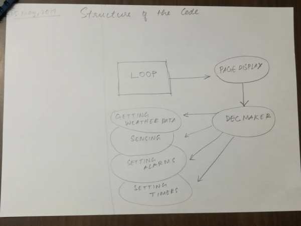
The total length of the code is about 550 lines.
The code is divided into two sects. One PageDisplay and the other DecMaker(short for decision maker). Whenever you hit any button, based on which(right or left), the LCD will display that page. When in that page and you hit the centerButton, then the code will move to the DecMaker. Inside the DecMaker function and based on which page was lastly open, the corresponding actions will execute. That may be getting weather data, sensing, setting alarms, and setting timers.
The pages are displayed according to the modes. The modes are four. They may be,
- Home mode – To get the weather data and display them. As well as sense the surroundings.
- Set timer mode – To set timers for you
- Set alarm mode – To set alarms for you
- Dashboard – When your not in any of the modes, you could rather stay in the dashboard.
That is how the code functions. Next, we will talk about the main sketch that you will be uploading to your weather box.
Step 9: The Main Code
The following is the main code.
To download the code, please click here.
LiquidCrystal lcd(16, 5, 4, 0, 2, 14);
#define rightButton 13
#define centerButton 15
#define leftButton 12
#define buzz 3
int page = 1;
<p>byte leftArrow[8]{<br>  B00000,
  B00010,
  B00110,
  B01110,
  B11110,
  B01110,
  B00110,
  B00010
};
byte rightArrow[8]{
  B00000,
  B01000,
  B01100,
  B01110,
  B01111,
  B01110,
  B01100,
  B01000
};</p><p>byte line[8] {<br>  B00110,
  B00110,
  B00110,
  B00110,
  B00110,
  B00110,
  B00110,
  B00110
};
String result;
char servername[]="api.openweathermap.org";
String APIKEY = "Your Api key";
String CityID = "Your city ID";</p><p>String Description;<br>String Place;
float Temperature;
float Humidity;
float w;</p><p>WiFiClient client;</p><p>dht DHT;<br>#define pin 1
int set=1; // for configuring the alarm
int a, b, c; // used to denote the hour, minute and second while setting an alarm</p>
<p>char username[] = "MQTT_username";<br>char password[] = "MQTT_password";
char clientID[] = "Client ID";
void setup() {
  // put your setup code here, to run once:
 Serial.begin(9600);
 WiFi.begin("ssid", "password");
 lcd.print("Weather box");
 delay(2000);
 lcd.clear();
 if (WiFi.status() == WL_CONNECTED){
 Cayenne.begin(username, password, clientID);
 lcd.print("Connected!");
 delay(3000);
 lcd.clear();
 Serial.println(WiFi.localIP());
 } else {
  lcd.print("Not conn");
  delay(3500);
 }
 lcd.clear();
 lcd.begin(16, 2);
 lcd.createChar(0, leftArrow);
 lcd.createChar(1, rightArrow);
 lcd.createChar(3, line);

 pinMode(rightButton, INPUT);
 pinMode(centerButton, INPUT);
 pinMode(leftButton, INPUT);
 pinMode(buzz, OUTPUT);
 digitalWrite(buzz, LOW);

 setTime(15, 12, 50, 25, 5, 17);
 delay(1000);
}
int val = 1;
int x,y; //for setting timer minutes and seconds
int trig; //for coniguring the timer
int counter = 0;
void loop() {
  // put your main code here, to run repeatedly:
  while(val == 1){
    if (digitalRead(leftButton)==HIGH)
    { val = 0;}
    lcd.clear();
    lcd.print(hour());
    lcd.print(":");
    lcd.print(minute());
    lcd.write(byte(3));
    lcd.print("WiFi:");
    if (WiFi.status() == WL_CONNECTED){
    lcd.print("conn"); }
    else {
    lcd.print("Nconn");}
    lcd.setCursor(0, 1);
    lcd.write(byte(0));
    lcd.print("Menu");
    lcd.write(byte(3));

    if (digitalRead(centerButton)){
      DHT.read11(pin);
      lcd.print("T:");
      int a = DHT.temperature; //converting float to int
      lcd.print(a);
      int b = DHT.humidity; // converting float to int
      lcd.print(" H:");
      lcd.print(b);
      delay(3000);
    }else {
      date();
    }
    counter++;
    if (counter == 60){
      if (WiFi.status()==WL_CONNECTED){
        Cayenne.loop();
        DHT.read11(pin);
        Cayenne.virtualWrite(1, DHT.temperature);
        Cayenne.virtualWrite(2, DHT.humidity);
      }
    counter = 0;
    }
    delay(50);
  }
  while (val != 1){
   delay(200);
   pageDisplay();
   if (digitalRead(rightButton)){
     if (page == 4){
       page = page;
     } else {
       page++;
     }
     pageDisplay();

    } else if (digitalRead(leftButton)){
     if (page == 1){
       page = page;
     } else {
       page--;
     }
     pageDisplay();

   } else if (digitalRead(centerButton)== HIGH){
     decMaker();
   }
  }
}</p>
<p>void pageDisplay(){<br>  switch(page){
    case 1:
    lcd.clear();
    lcd.setCursor(6, 0);
    lcd.print("Home");
    lcd.setCursor(15, 0);
    lcd.write(byte(1));
    break;
    case 2:
    lcd.clear();
    lcd.write(byte(0));
    lcd.setCursor(3, 0);
    lcd.print("Set Timer");
    lcd.setCursor(15, 0);
    lcd.write(byte(1));
    break;
    case 3:
    lcd.clear();
    lcd.write(byte(0));
    lcd.setCursor(3, 0);
    lcd.print("Set Alarm");
    lcd.setCursor(15, 0);
    lcd.write(byte(1));
    break;
    case 4:
    lcd.clear();
    lcd.write(byte(0));
    lcd.setCursor(3, 0);
    lcd.print("Dash Board");
    break;
    default:
    lcd.clear();
    lcd.print("Error 002");
    break;
  }
}
void date(){
  lcd.print(day());
  lcd.print(" ");
  int a = month();
  switch(a){
    case 1:
    lcd.print("Jan");
    break;
    case 2:
    lcd.print("Feb");
    break;
    case 3:
    lcd.print("Mar");
    break;
    case 4:
    lcd.print("Apr");
    break;
    case 5:
    lcd.print("May");
    break;
    case 6:
    lcd.print("Jun");
    break;
    case 7:
    lcd.print("Jul");
    break;
    case 8:
    lcd.print("Aug");
    break;
    case 9:
    lcd.print("Sep");
    break;
    case 10:
    lcd.print("Oct");
    break;
    case 11:
    lcd.print("Nov");
    break;
    case 12:
    lcd.print("Dec");
    break;
    default:
    lcd.print("005");
  }
    if (day()<10){
  lcd.print(" ");
  }
  lcd.print(year());
  }</p><p>void decMaker(){<br>  switch(page){
      case 1:
      lcd.clear();
      lcd.print(". . .");
      weatherData();
      lcd.clear();
      while (digitalRead(leftButton) == LOW){
        weatherData();
        digitalRead(leftButton);
        lcd.setCursor(6, 0);
        lcd.print("IST:");
        lcd.setCursor(5, 1);
        lcd.print(hour());
        lcd.print(":");
        lcd.print(minute());
        delay(3000);
        lcd.clear();
        lcd.print("Wthr in ");
        lcd.print(Place);
        lcd.setCursor(0, 1);
        lcd.print("T:");
        lcd.print(Temperature);
        lcd.setCursor(9, 1);
        lcd.print("H:");
        lcd.print(Humidity);
        delay(3000);
        lcd.clear();
        digitalRead(leftButton);
        lcd.print("Wind: ");
        lcd.print(w);
        lcd.print("kmph");
        lcd.setCursor(0, 1);
        lcd.print(Description);
        delay(2000);
        lcd.clear();
        DHT.read11(pin);
        lcd.print("Room: ");
        lcd.setCursor(0, 1);
        lcd.print("T:");
        lcd.print(DHT.temperature);
        lcd.setCursor(9, 1);
        lcd.print("H:");
        lcd.print(DHT.humidity);
        delay(2000);
        lcd.clear();
      }
      lcd.begin(16, 2); // In my case the lcd doesn't work without this. But don't know why.
      break;
      case 2:
      setTimer();
      break;
      case 3:
      setAlarm();
      Serial.print("THREE");
      lcd.begin(16, 2);
      break;
      case 4:
      Serial.print("FOUR");
      val = 1;
      break;
      default:
      Serial.print("not a valid entry");
      lcd.clear();
      lcd.print("error 001");
      break;
   }
}</p><p>void weatherData(){<br>    if (client.connect(servername, 80)) {  //starts client connection, checks for connection
    client.println("GET /data/2.5/weather?id="+CityID+"&units=metric&APPID="+APIKEY);
    Serial.println("Server is accessable");
    client.println();
  }
  else {
    Serial.println("connection failed"); //error message if no client connect
    Serial.println();
  }
  result = "";
  while (client.available()) { //connected or data available
    char c = client.read(); //gets byte from ethernet buffer
      result = result+c;
    }
  result.replace("[", " ");
  result.replace("]", " ");
  client.stop(); //stop client
  Serial.println("Recieved");

 StaticJsonBuffer<1024> jbuff;
 JsonObject &root = jbuff.parseObject(result);
 if (!root.success())
 {
  Serial.println("parseObject() failed");
 }</p><p>String location = root["name"];<br> float temperature = root["main"]["temp"];
 float humidity = root["main"]["humidity"];
 String description = root["weather"]["description"];
 float wind = root["wind"]["speed"];</p><p>Place = location;<br> Temperature = temperature;
 Humidity = humidity;
 w = wind * 3.6;
 Description = description;
}</p><p>void alarm(){<br>  Serial.println("Alarm activated");
  lcd.clear();
  lcd.print("Wake up, Lazy");
  for (int i = 0; i <= 10; i++){
    digitalWrite(buzz, HIGH);
    delay(80);
    digitalWrite(buzz, LOW);
    delay(80);
    digitalWrite(buzz, HIGH);
    delay(80);
    digitalWrite(buzz, LOW);
    delay(800);
  }
  digitalWrite(buzz, LOW);
  set = 0;
}
void setAlarm(){
  set = 1;
  int pos = 1;
  a, b, c = 0;
  repeat:
  //timeDisplay();
  lcd.clear();
  lcd.setCursor(0, 0);
  lcd.print(a);
  lcd.print(":");
  lcd.print(b);
  lcd.print(":");
  lcd.print(c);
  lcd.setCursor(0, 1);
  if (pos == 1){ lcd.print("hours");}
  else if (pos == 2){ lcd.print("minutes");}
  else if (pos == 3){lcd.print("seconds");}
  delay(200);
  if (digitalRead(leftButton)){//leftButton
    if (pos == 3)
    {pos = 1;}
    else
    {pos++;}
  } else if (digitalRead(rightButton)){
    switch (pos){
      case 1:
      if (a == 23){ a = 0;}
      else {a++;}
      break;
      case 2:
      if (b == 59){ b = 0;}
      else {b++;}
      break;
      case 3:
      if (c == 59){ c = 0;}
      else {c++;}
      break;
      }
  } else if (digitalRead(centerButton)){
    confirmAlarm();
  }
  if (set == 0){
    goto endIt;
  }
  goto repeat;
  endIt:
  Serial.println("Alarm executed successfully");
}</p><p>void confirmAlarm(){<br>  lcd.clear();
  Alarm.alarmOnce(a, b, c, alarm);
  up:
  lcd.setCursor(1, 0);
  lcd.print("Alarm Running");
  lcd.setCursor(3, 1);
  lcd.print(hour());
  lcd.print(":");
  lcd.print(minute());
  lcd.print(":");
  lcd.print(second());
  Alarm.delay(200);
  delay(1);
  lcd.clear();
  //timeDisplay();
  Serial.println("...");
  if (set == 0||digitalRead(centerButton)){goto down;}
  goto up;
  down:
  set = 0;
}</p><p>void setTimer(){<br>  int cur = 1;
  x, y = 0;
  trig = 1;
  roof:
  lcd.clear();
  lcd.setCursor(2, 0);
  lcd.print("minutes: ");
  lcd.print(x);
  lcd.setCursor(2, 1);
  lcd.print("seconds: ");
  lcd.print(y);
  if (cur == true){lcd.setCursor(0, 0); lcd.write(byte(1));}
  else {lcd.setCursor(0, 1); lcd.write(byte(1));}
  delay(200);
  if (digitalRead(rightButton)){
    switch(cur){
      case 1:
      if (x == 20){x=0;}
      else {x++;}
      break;
      case 2:
      if (y == 59){y = 0;}
      else {y++;}
      break;
      default:
      lcd.clear();
      lcd.print("ERROR 003");
    }
  } else if (digitalRead(leftButton)){
    if (cur == 2){cur = 1;}
    else {cur++;}
  }
   if (digitalRead(centerButton)){
     confirmTimer();
   } else {
    goto roof;
   }
   trig = 0;
   lcd.setCursor(0, 0);
   lcd.print("Timer successful");
   delay(2000);
   lcd.clear();
}</p><p>void confirmTimer(){<br>  int z;
  z = x*60 + y;
  Alarm.timerOnce(z, timer);
  lcd.clear();

  sky:
  Serial.println(".");
  lcd.clear();
  lcd.setCursor(0, 0);
  lcd.print("CountDown Timer");
  lcd.setCursor(7, 1);
  lcd.print(z);
  z--;
  Alarm.delay(999);
  delay(1);
  if (trig == 0||digitalRead(centerButton)==HIGH){goto ground;}
  goto sky;
  ground:
  trig = 0;
  lcd.clear();
}
void timer(){
  Serial.println("Boom, timer is on!! :)");
  lcd.clear();
  lcd.setCursor(3, 0);
  lcd.print("Time's Up!");
  for (int i = 0; i<=10; i++){
    for (int j = 0; j<=3; j++){
      digitalWrite(buzz, HIGH);
      delay(70);
      digitalWrite(buzz, LOW);
      delay(70);
    }
    delay(700);
  }
  trig = 0;
}</p>
Step 10: Conclusion
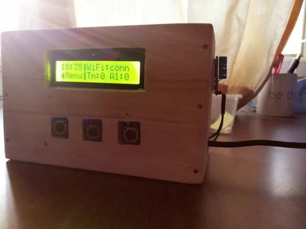
Hence, our weather box is now complete. It makes me very happy to know if you’ve come so far to learn about my summer project! The box could slightly be altered and hung on the wall with a constant power supply and you could enjoy what it could do for you. Umm..i am using a power bank temporarily but soon in future maybe i will use a wall socket as it’s permanent power supply showcase it somewhere.
Right after uploading the code, the box will thrive to life. So guys thank you so much for taking part in this tutorial and don’t forget to vote for me in the contests i have entered. Hope you enjoyed and comment below what you feel about this weather box of mine.
Source: IoT: Weather Box (with Custom Alarms & Timers)
- What is the primary function of the Weather Box?
The device displays weather information, keeps alarms and timers, and shows the time and date. - How does the device fetch weather data?
It connects to the internet via WiFi and retrieves data from openweathermap.org using an API key. - Can I view my local weather information remotely?
Yes, you can use an MQTT server like Cayenne to upload sensor data and view it from anywhere. - Which libraries are required for the code?
You need LiquidCrystal, ESP8266WiFi, ArduinoJson, Time, TimeAlarms, and CayenneMQTTESP8266 libraries. - What material was used to build the enclosure?
The author used 0.5mm plywood and Fevicol glue to construct the wooden box. - How many push buttons are needed for the project?
The project requires three push buttons labeled LeftButton, CenterButton, and RightButton. - Does the DHT11 sensor stay inside the box?
No, the DHT11 sensor stays outside the box to sense the external temperature. - What happens when an alarm or timer is triggered?
The buzzer activates by turning high and low repeatedly to signal the user.