Summary of Arduino Traffic Light Controller with Remote Control
This article details the construction of an Arduino-based traffic light controller featuring remote control capabilities. The project defines parameters for three sequenced outputs and four inputs, utilizing an Arduino Duemilanov to manage LED patterns and timing via buttons and a remote receiver. The author emphasizes prototyping, coding in C-like syntax, and thorough testing before finalizing the electronic schematic design with transistors and relays.
Parts used in the Arduino Traffic Light Controller:
- Arduino Duemilanov
- 3 LEDs
- 4 switches
- Remote control receiver
- Switching transistors
- 5 volt relays
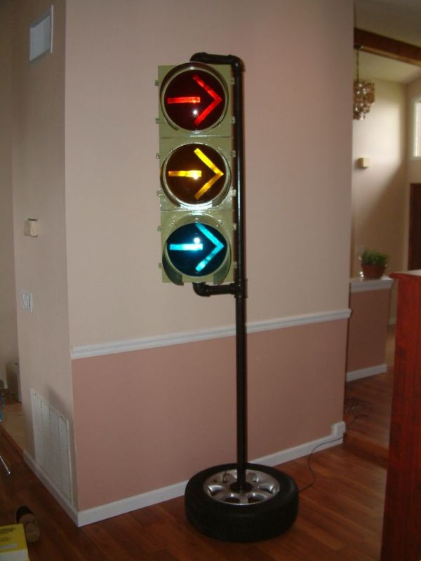
I had a traffic light that I was refinishing. The only thing left to do was to build the controller for the light’s signal patterns. To give it a twist I incorporated a remote control. This was also the perfect opportunity for me to try out an Arduino. I wanted to use the Arduino becuase it was easy to use on both MAC and Windows.
Step 1: Define the Project
To start an electronics design project first define the parameters of it functionality.
This project is defined as:
Control 3 outputs
Read 4 inputs
Read 1 interupt
Features:
3 outputs are sequenced in multiple modes
-Standard Traffic Light pattern
-Reversed Pattern
-Steady on each output
-Blink each output
-Turn off
Increment and decrement sequence speed
Modify saved timing parameters using remote control
and most important; Execute in a realtime manor.
Step 2: Prototype the circuit
Use prototype methods to test the circuit.
I used the Arduino Duemilanov. I attached 3 LED’s , 4 switches and began to write the code. The Arduino IDE (which is FREE!!) uses a syntax that is very similar to good old fashioned ANSI C. I started with the modes of signal patterns. I used a case statement to modularize my code. I the added the code for the buttons. The buttons control mode UP/DN and speed UP/DN.
Step 3: Write the code
 traffic.pde7 KB
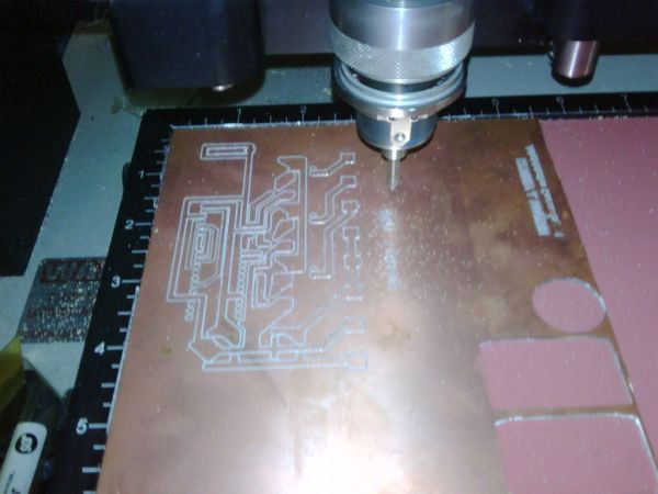
Step 4: TEST TEST TEST TEST
Test your circuit and code thoroughly.
The Arduino allows for field program ability, but that is no excuse for not testing.
After adding the remote control I had alot of code changes in order to operate the code.
This version has usable code for the remote’s receiver but it breaks the ability to reprogram the timing and default flash pattern and speed at power up.
Step 5: Electronic Schematic Design
Create each component and connect their pins together
 TrafficLightSch.pdf(612×792) 28 KB
3 LED’s
For more detail: Arduino Traffic Light Controller with Remote Control
- What programming language syntax does the Arduino IDE use?
The Arduino IDE uses a syntax very similar to good old fashioned ANSI C. - How are the output pins buffered in this circuit?
The output pins are buffered using switching transistors that drive 5 volt relays. - Where is the signal received line from the remote connected?
The signal received line is connected to the interrupt pin on the Arduino. - Can this project be programmed on both MAC and Windows?
Yes, the Arduino was chosen because it is easy to use on both MAC and Windows. - Does the code use a case statement for modularization?
Yes, the code uses a case statement to modularize the modes of signal patterns. - What happens if you add the remote control without adjusting the code?
Adding the remote control breaks the ability to reprogram the timing and default flash pattern at power up. - How many outputs and inputs does the project define?
The project is defined to control 3 outputs and read 4 inputs plus 1 interrupt. - Is the Arduino IDE free to use?
Yes, the article states that the Arduino IDE is FREE.