About a year ago, I felt like some rooms in my house were colder than other ones. I wanted to check for sure, so I built a few temperature and humidity sensors connected to my phone via wifi, and dispersed them in my house.
I could simply have picked up one thermometer, and moved it from room to room, but this way I can better see the temperature in real time, I can see how they evolve through the week or through the year, and I can see if the temperature in a room is completely off compared to the other ones. Plus, I can check the temperature and humidity when I’m away.
I wanted something very simple with no bells and whistles. I also wanted something small and neat looking since it will be installed permanently, this is why I designed my PCB, instead of using a breadboard.
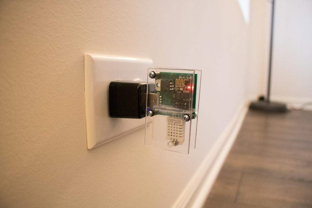
My sensor simply plugs in a USB outlet to get the 5V power, this way there is no battery to change or recharge.
I am using and ESP8266 for the wifi connection because of its small size and cheap price.
I use the Blynk app to view the temperature and humidity on my phone, because of its simplicity of use, and because I already use this app for other IoT stuff in my house.
The total price per piece is about 23$ (not including shipping costs). Of course it can be cheaper or more expensive depending on where you source your components, and if you buy them in bulk.
Supplies:
- DHT22 temperature and humidity sensor
- ESP8266 wifi microcontroller
- LD1117V33 3.3V regulator
- 2x 10uF capacitors
- 10k resistor
- USB male type A connector
- custom-made PCB (or a solderable breadboard would work too)
- some female headers
- some 1/8″ plexiglass
- a few PCB standoffs
Tools:
- Soldering iron
- Drill
- Eagle for PCB design
- an FT232RL USB to TTL Converter Module (to upload the code to the ESP8266)
Step 1: Design and Order Your PCB
Since I wanted a neat-looking and compact sensor, I decided to design and order my own PCB instead of using a breadboard. I used the Autocad Eagle software to design the PCB. It is free for personal use by hobbyists, with a few limitations (2 schematic sheets, 2 signal layers, and an 80cm2 board area, which is plenty enough for my needs). I usually first work on the schematics, and then on the board.
Schematics
What I do is that I first place all the components that I will need using the “add tool” button. I make sure that I have the Adafruit and Sparkfun libraries, which is where I order most of my components. These libraries are downloadable from GitHub:
www.github.com/adafruit/Adafruit-Eagle-Library
www.github.com/sparkfun/SparkFun-Eagle-Librari…
Then I assemble the components by groups, such as power supply, sensors, microcontrollers, etc. Finally I link the components together, rotate them and move them around so that the scheme is easily readable.
In this example, the schematics is pretty straight forward. The power supply is 5V (from USB), but the ESP8266 uses 3.3V, hence the 3.3V regulator. I placed a capacitor on both the 5V and 3.3V. The DHT22 sensor is connected to 3.3V, ground, and the ESP’s GPIO2. There is also a pullup resistor using the 10k resistor.
I found the following resource to be helpful when it comes to designing the schematics on Eagle: www.learn.sparkfun.com/tutorials/using-eagle-schematic
Board
Once the schematics is done, I start working on the board. The components and their connections are already placed automatically, but I still check them to make sure that there is no mistake.
I then rearrange the components to avoid the paths criss-crossing, and to make the paths as short as possible.
I then route the connections, using an appropriate width for the traces and clearance, and making sure that they are within the capabilities of the PCB manufacturer.
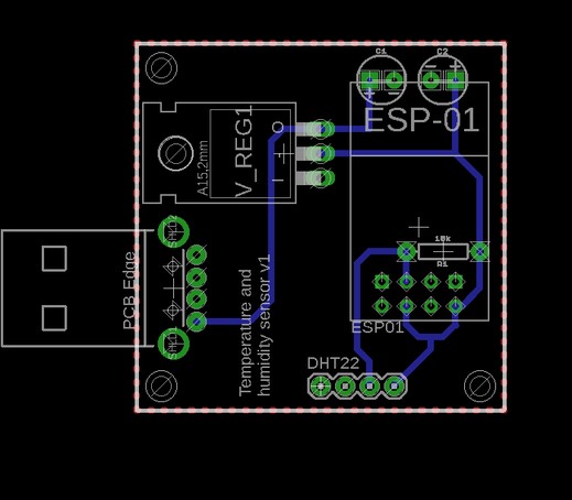
In this example, I have a ground plane at the back of the PCB, which is delimited by the dotted red line. To do this, I used the polygon tool.
The ESP8266 is clipped on female headers, which are soldered to the PCB. This way, the ESP8266 can be removed and reprogrammed down the road. This leaves quite some room below the ESP8266, where the resistor and the 2 bent capacitors can fit.
I wanted the DHT22 sensor to protrude from the PCB, so that any heat generated by the different components would have a minimal effect on the sensor measurements.
The usb male connector protrudes from the PCB, because it will be plugged in a USB socket. The component indicates where the PCB edge should be, which is quite convenient.
I then added holes in 3 corners to add standoffs, to which a plexiglass cover will be attached.
I found the following resource to be helpful when it comes to designing the board on Eagle: www.learn.sparkfun.com/tutorials/using-eagle-board-layout
Manufacturing
Once you are pleased with your board, extract the Gerber files, and send them to a PCB manufacturer. Make sure you follow the manufacturer’s requirements on how to send the files, and which files to send.
In my case I used PCBWay, they are super cheap, especially if the PCB does not have any special feature (such as multiple layers, or super thick or super thin layers), and if you are not in a hurry to get your PCB, the shipping cost is affordable.
Step 2: Program Your ESP8266
I used the Arduino IDE to program my ESP8266. It can be tricky to program this microcontroller, so I would recommend following this tutorial:
www.whatimade.today/esp8266-easiest-way-to-program…
Don’t forget to reset your ESP and connecting GPIO0 to ground before uploading your code.
I used an FT232RL USB to TTL Converter Module to upload the code to my ESP.
The code:
I used the example testing sketch that is supplied with the DHT sensor library by Adafruit, and adjusted the following:
- For the humidity and temperature values to be sent to the Blynk app, I added the following:
#include <BlynkSimpleEsp8266.h>
char auth[] = "your-32-characters-authorization-code";
and in the setup function:
Blynk.begin(auth, ssidChosen, passChosen, ip, 8442);
while(Blynk.connect() == false);
- I added some code to connect to the wifi. With the following code, I am able to save several known wifi’s, and the ESP looks if one of the known wifi’s is available. Also, if no known wifi is available, it keeps looking for one. This way, after a power outage, my sensors wake up, and wait for my wifi router to wake up (my router is a little slower to wake back up after a power outage):
#include <ESP8266WiFi.h>

char* ssid[] = {"SSID1", "SSID2"};
char* pass[] = {"PASSWORD1", "PASSWORD2"};
const int nbKnownAP = 2;//number of elements in ssid[] and pass[]
char ssidChosen[20] = "\0";//increase the number of characters if longest ssid is longer than 20 characters
char passChosen[20] = "\0";//increase the number of characters if longest pass is longer than 20 characters
IPAddress ip (45,55,96,146);
And in the setup function:
int numSsid = 0;//Number of ssid found
int i = 0;
int j = 0;

do{
    Serial.println("** Scan Networks **");
    numSsid = WiFi.scanNetworks();
    if (numSsid == -1)//In case there is no wifi connection
      Serial.println("No wifi signal found");

    // print the list of networks seen:
    Serial.print("number of available networks:");
    Serial.println(numSsid);

    // print the network number and name for each network found:
    for (i = 0; i < numSsid; i++){
      Serial.print(i);
      Serial.print(") ");
      Serial.print(WiFi.SSID(i));
      Serial.print("\tSignal: ");
      Serial.print(WiFi.RSSI(i));
      Serial.println(" dBm");
      for(j=0; j<nbKnownAP; j++){
        if(WiFi.SSID(i) == ssid[j]){//in case 1 of the networks found is a known network
          Serial.print(ssid[j]);
          Serial.println(" is a known network!");
          strcpy(ssidChosen, ssid[j]);
          strcpy(passChosen, pass[j]);
        }
      }
    }

    if(strlen(ssidChosen) == 0){//in case no known network was found
      Serial.println("None of the known networks has been found. Restarting loop.");
      delay(2000);
    }
  } while(strlen(ssidChosen) == 0);

  Blynk.begin(auth, ssidChosen, passChosen, ip, 8442);
  while(Blynk.connect() == false);
- I used a timer to measure temperature and humidity values, instead of the delay function. The reason is that it is not advised to use a blocking function such as delay() in the loop, along with the Blynk library:
BlynkTimer timer;

void sendData(){
  float h = dht.readHumidity();
  float f = dht.readTemperature(true);

  // Check if any reads failed and exit early (to try again).
  if (isnan(h) || isnan(f)){
    Serial.println("Failed to read from DHT sensor!");
    return;
  }

  Serial.print("Humidity: ");
  Serial.print(h);
  Serial.print(" %\t");
  Serial.print("Temperature: ");
  Serial.print(f);
  Serial.print(" *F\n");

  Blynk.virtualWrite(V0, h);//sends humidity value to virtual pin V0
  Blynk.virtualWrite(V1, f);//sends temperature value to virtual pin V1<br>
}
and in the setup function:
timer.setInterval(60000L, sendData);
and in the loop function:
timer.run();
I attached the full Arduino sketch as a file, just insert your known SSIDs in ssid[], your known wifi passwords in pass[], the number of known SSIDs and passwords in nbKnownAP, and your 32-characters Blynk authorization code in auth[] (this code is given to you by the Blynk app).
Step 3: Assemble Your Board
Assembling the components on the board is the fun part! Simply heat up your soldering iron, place your components, and solder them.
Just remember that you solder the female headers to the board, not the actual ESP8266.
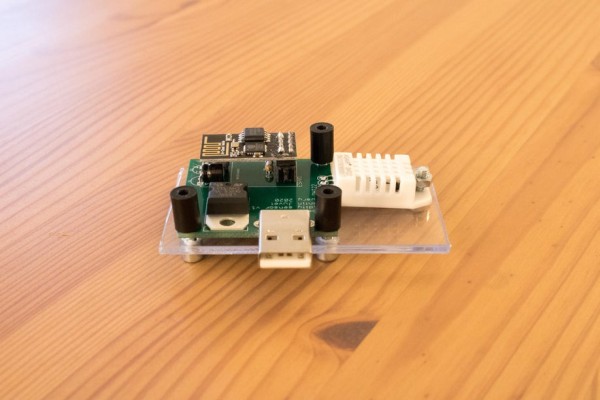
The capacitors are bent under the ESP8266, otherwise it won’t fit.
The sensor is bent outside of the board (away from the heat sources)
Once everything is soldered, install the standoffs at the 3 locations. Cut 2 pieces of plexiglass, the size of the assembly. Drill holes in the plexiglass at the same locations as the standoffs, plus one hole that will be used to hold the DHT22 down. Cut a small piece of plexiglass the same width as the standoffs, and glue it to the top piece using CA glue. This is to prevent heat sources on the board from affecting the temperature readings. Screw the bottom and top pieces of plexiglass to the standoffs.
Then plug it in a usb socket, or usb charger.
Source: IoT Temperature and Humidity Sensors