
Summary of MODERN TUBE TESTER USES ARDUINO
[Usagi] built a custom tube tester operating at 24V to suit specific low-voltage projects, differing from traditional high-voltage units. The circuit utilizes a 555 charge pump for negative voltage generation and an Arduino for bias control and measurements via a voltage divider. Data is exported to spreadsheets for curve tracing. While currently application-specific, future plans include a general-purpose design potentially using punched cards for flexible pinout connections.
Parts used in the Custom Tube Tester:
- 24V power supply
- 555 charge pump
- Arduino microcontroller
- Voltage divider
- Tube under test
There was a time when people like us might own a tube tester and even if you didn’t, you probably knew which drug store had a tube testing machine you could use for free. We aren’t sure that’s a testament to capitalistic ingenuity or an inditement of tube reliability — maybe both. As [Usagi] has been working on some tube-based projects, he decided he needed a tester so he built one. You can see the results in the video, below.
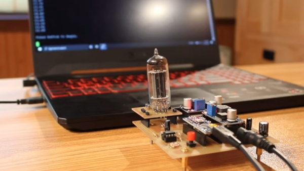
The tester only uses 24V, but for the projects he’s building, that’s close to the operation in the real circuits. He does have a traditional tube tester, but it uses 100s of volts which is a different operating regime.
The bulk of the circuit is creating the voltages required, including a 555 charge pump to generate around -10V. The tube is wired up in a particular configuration and the Arduino makes a few measurements while changing the operating bias conditions. The converter goes through a voltage divider so the maximum 24 volts won’t overload the Arduino.
Grabbing the data into a spreadsheet allowed some curve tracing which looked useful for matching. However, as [Usagi] points out, the tester is very specific to his application. He has plans to maybe make a more general-purpose tube tester.
One of the problems with a truly general-purpose tube tester is connecting to the different pinouts. Punched cards offered one answer. If you don’t remember tube testers in drug stores, you might find that TV repair, at one time, was a big business.
Source: MODERN TUBE TESTER USES ARDUINO
- What voltage does the custom tube tester use?
The tester operates using 24V. - How is the negative voltage generated in the circuit?
A 555 charge pump generates approximately -10V. - Which component controls the operating bias conditions?
The Arduino makes measurements while changing the operating bias conditions. - How is the maximum 24 volts protected from overloading the Arduino?
The converter goes through a voltage divider to prevent overload. - What method was used to analyze the collected data?
Data was grabbed into a spreadsheet to allow for curve tracing. - Is this tester designed for all types of tubes?
No, the tester is very specific to the current application. - What historical technology might be used for a general-purpose pinout connection?
Punched cards offered one answer for connecting to different pinouts. - Does the author plan to expand the project?
Yes, there are plans to make a more general-purpose tube tester.
