
The need for such modernization arose when used in remote buildings located near a country house.
Adults and especially children turned on and forgot to turn off the lamp. As a result, the batteries drained quickly. I decided to replace the incandescent bulb with more economical and efficient LEDs and limit the lamp run time.
The time limiter has the following features:
- Very short code: 806 bytes fit on a cheap 8-pin ATtiny13A microcontroller
- Very simple operation: just press the button to start.After the countdown, there is a gradual decrease in the brightness of the LEDs before turning off.Fall asleep at the end.
- Early shutdown at the touch of a button during the countdown.
- Two possible values of the glow time of the lantern: 3 or 10 minutes (set by a jumper).
- Very low power consumption in sleep mode, no need to explicitly turn off the power.
Step 1: Components and Tools
Most of these components I received from AliExpress for about 2 USD.
- ATtiny13A microcontroller.
- 8-pin IC connector.
- Transistor MOSFET IRLML2502.
- DIP16 to SO16 adapter board (or 3×4 cm prototype board).
- Resistor 1/4 W 10k Ohm.
- Resistor 1/4 W 1k Ohm.
- Resistor 1/4 W 100 Ohm.
- Ceramic capacitor 100 nf.
- Indicator LED.
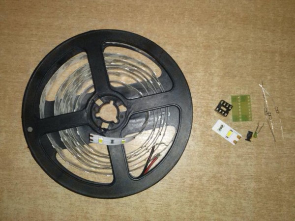
- LED tape (with adhesive base).
- Some stranded hookup wire to connect everything.
- Old portable wall lamp on batteries.
Required tools:
- Soldering iron
- Arduino Uno for ATtiny13 programming
- Gun with hot glue to fix the board in the lamp.
Step 2: Schematic Image
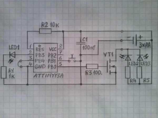
The schematic is shown in the picture.I would recommend trying it out on a bredboard first.
3xAA batteries supply enough voltage and current to operate the device.
Pin 6 ATtiny is connected to the ground with a button to turn on the lamp. Pin 3 ATtiny is used to quickly change the glow time of the lamp. When connected to ground, the time is limited to 3 minutes. If pin 3 is free, the glow time is 10 minutes. In general, it is always possible to change the time required in the sketch and program new values in the microcontroller. The LED connected to pin 2 flashes during the countdown. Pin 5 controls the MOSFET transistor connected to the LEDs on the tapes.
Step 3: The Code
The code is attached. It was written as a sketch under the Arduino IDE. Follow other instructions on how to program the ATtiny using an Arduino Uno. A brief summary is below:
- The easiest way to program an ATtiny chip is to use an Arduino as ISP (In System Programmer). Follow the following steps:
- Starting up the Arduino IDE, open ‘Preferences’ then add https://mcudude.github.io/MicroCore/package_MCUdu… for additional board managers.
- Under ‘Tools/Board’, select ‘Board Manager’ and at the bottom of the list, install ‘MicroCore by MCUdude’
- Connect the Arduino Uno and upload ‘ArduinoISP’. It is available under ‘File/examples’
- Connect the Arduino to the ATtiny, easiest done by putting the ATtiny on a prototype shield: Arduino pin 13 – ATtiny pin 7 Arduino pin 12 – ATtiny pin 6 Arduino pin 11 – ATtiny pin 5 Arduino pin 10 – ATtiny pin 1 Arduino +5v – ATtiny pin 8 Arduino GND – ATtiny pin 4
- Choose ‘Board ATtiny13’, ‘B.O.D disabled’, ‘Clock 1.2 MHz internal’ and programmer ‘Arduino as ISP’. Do ‘Burn Bootloader’ – there is no bootloader for the attiny, and it may give an error, but this step is needed to ‘set the fuses’ to the correct clock setting
- Upload the attached Tinyledvartimer.ino
Step 4: Mount It in the Lamp
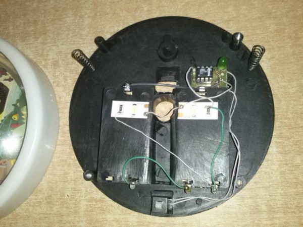
Once you have launched the device on the scale board, you will need to place it in the middle of the lamp. Here’s what to do:
Solder the 8-pin IC holder to the adapter board (or prototype board) of the required size and other components. Leave the terminals of resistors R1, R2 long to solder the power wires. Unscrew the screws and open the lamp you are upgrading, remove the incandescent bulb. Cut two strips from the LED strip (each with 1 LED and a resistor). Remove the protective layer from the bottom and glue the strips in the center inside the lamp. Place the board near the LED strips. Measure and cut the wires. For the normal operation of the device requires a button without locking (I disassembled and removed the latch from the lamp button). Solder the power and control wires to the board. The board fixed better with some hot glue. Insert the programmed ATtiny, the batteries and turn it on. If this works, close the lamp and start using it.
See some images for intermediate steps.
Source: Lamp Mod With the ATtiny13