
Summary of IoT Robotic Arm
This project demonstrates a robotic arm controlled via the free Blynk mobile app, ideal for IoT beginners. It utilizes multiple servo motors to manage various axes and rotations, enabling tasks like handling radioactive materials or operating switches where human presence is unsafe. The system integrates NodeMCU with Arduino IDE for programming and connects hardware components through specific soldering and wiring configurations to ensure precise remote operation.
Parts used in the Robotic-arm controlled by a mobile application known as BLYNK:
- NodeMCU
- Servo motors
The project is Robotic-arm controlled by a mobile application known as BLYNK; it is free and…
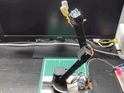
Description
Description:-
The project is Robotic-arm controlled by a mobile application known as BLYNK; it is free and easy to use for automation and IoT projects for beginners. In this project, multiple servo control different axes and rotation of the arm in a different direction. This project can be used where human intervention is not possible, it can attach to a remote-controlled rover. It can carry radioactive stuff, turn on-off the switch, carry a light load, push-pull lever.
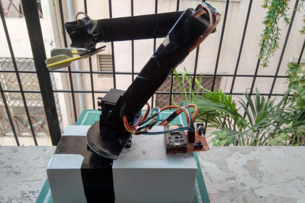
Project Used Hardware
NodeMCU, servo motors
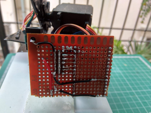
Project Used Software
ArduinoIDE, BLYNK
Circuit Diagram
1. Solder female pin on PCB for NodeMCU.
2. Solder male header for all servo.
3. Connect each digital pin to the servo control signal pin.
4. Connect the common ground of all servo and NodeMCU to DC jack GND.
5. Connect all Vcc of servo and NodeMCU(Vin) pin to Vcc pin of DC jack through a sliding switch.
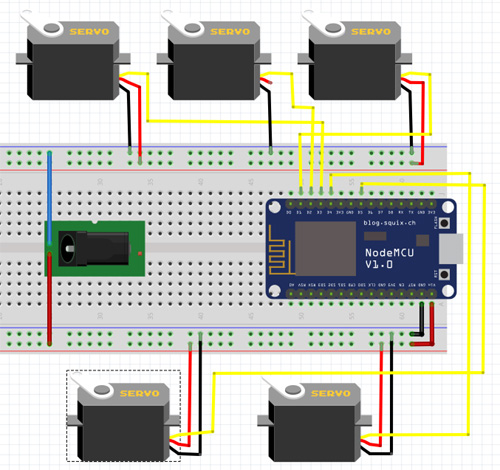
Source: IoT Robotic Arm
- What software is required for this project?
The project uses ArduinoIDE and BLYNK. - Can this robotic arm be attached to a rover?
Yes, it can attach to a remote-controlled rover. - Is the BLYNK application free to use?
Yes, the BLYNK application is free and easy to use. - How are the digital pins connected to the servos?
Each digital pin connects to the servo control signal pin. - Where should the common ground of all servos be connected?
The common ground connects to the DC jack GND along with the NodeMCU. - What component controls the power connection between Vcc and the DC jack?
A sliding switch connects the Vcc pin of the DC jack to the Vcc of the servo and NodeMCU. - What tasks can this robotic arm perform?
It can carry radioactive stuff, turn on-off switches, carry light loads, and push-pull levers. - Which microcontroller is used in this project?
The project uses a NodeMCU.
