
The power tracker is an IOT based device that helps us to keep track of our power consumption. It also alerts us when we are exceeding the power usage limit. With this device, we don’t have to wait until the end of the month to know our power usage. Daily usage alert helps us control our power consumption.
This is a small compact device that we just have to attach on to our power meter.
You might have observed a LED on our meter that keeps blinking, have you ever wondered why?
This LED actually blinks according to our power consumption. We can observe that the LED blinks rapidly when the power usage is high and slows down when we switch off our home appliances.
Power tracker reads the pulse frequency using an LDR, converts it into watts and then sends it to our phone with the help of the wifi module.
In this project, we use blynk as a digital dashboard to display power usage and to make alerts. Blynk is an internet of things platform used to link sensors connected to devices like Arduino, nodmcu to mobile phones. To know more about Blynk please visit the page.
We will be using the Blynk app and library to implement this project. The Blynk server/cloud is responsible for all the communications that happen between the smartphone and the hardware.
Circuit and working
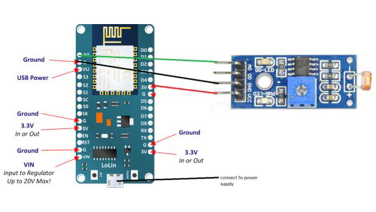
The circuit is very simple all we have to do is connect an LDR module to NodeMcu as shown above.
The Nodemcu is a micro control unit that has an ESP8266 integrated into it. The Programs can be uploaded into it using the Arduino IDE, you can download the IDE from ardrino.cc.com.
We also need drivers for ESP8266 which you can download from silabs.com. The driver is needed so that we can communicate with the development board ( NodeMcu ).
In this project, the NodeMcu is programmed to monitor the power with the help of an LDR module.
LDR module is readily available in online shops.
The LDR is basically a light sensitive resistor that changes its resistance according to the light. It is made of a light sensitive semiconductor.
LDR module is wired to produce a change in its output potential when LDR resistance changes . We have programmed the nodemcu to detect the change in potential and convert it into power unit (watts).
The code
#include
#include
const char* ssid = “name”;//add the hotspot name here
const char* password = “password”;
const char* host = “data.sparkfun.com”;
const char* streamId = “………………..”;
const char* privateKey = “………………..”;
char auth[] = ” f444ef88f92a4d7dafd08b54261b3ea3″;// add the auth token genetrated from unsigned long previousmillis=0,time1; //the blynk app here
int pulsestate=0,count=0;
int counter=0,w=100;
void setup() {
Serial.begin(115200);
delay(10);
// We start by connecting to a WiFi network
/*
Serial.println();
Serial.println();
Serial.print(“Connecting to “);
Serial.println(ssid);
WiFi.begin(ssid, password);
while (WiFi.status() != WL_CONNECTED) {
delay(500);
Serial.print(“.”);
}
Serial.println(“”);
Serial.println(“WiFi connected”);
Serial.println(“IP address: “);
Serial.println(WiFi.localIP());
*/
pinMode(A0, INPUT);
Blynk.begin(auth,ssid,password);
}
int value = 0;
int inactivecount=0;
void loop() {
unsigned long currentmillis=millis(); // t
// put your main code here, to run repeatedly:
Serial.println(“loop”);
int x = analogRead(A0); //Reads the analog value on pin A3 into x
Serial.println(x); // detecting the state of the led ie on /off
if(x<=100)
{
pulsestate=1;
} else {
pulsestate=0;
count=0;
}
inactivecount++;
if(pulsestate==1&&count==0){
time1=(currentmillis-previousmillis)/1000;
previousmillis=currentmillis;
if(time1<=1){
inactivecount=0;
w=3600;}
else if(time1<=1.5)
w=2400;
else if(time1<=2)
w=1800;
else if(time1<=3)
w=1200;
else if(time1<=4)
w=900;
else if (time1<=5)
w=720;
else if(time1<=6)
w=600;
else if (time1<=8)
w=450;
else if(time1<=10)
w=360;
else if (time1<=15)
w=240;
else if(time1<=20)
w=180;
else if (time1<=30)
w=120;
else if(time1<=60)
w=60/1000;
else if (time1<=120) w=30/1000; delay(100); count=1;} if(counter%10==0){ Blynk.virtualWrite(V2, counter); Blynk.virtualWrite(V1, x); Blynk.virtualWrite(V3, w); // to display the watt in blynk if(w>2000)
{Blynk.notify(“POWER USAGE HIGH”);
Blynk.email(“[email protected]”,”power consuption”,”High power usage”);}
}
counter++;
Serial.print(“time:”);
Serial.println(time1);
Serial.print(“Light”);
Serial.println(x);
Serial.print(“watt”);
Serial.println(w);
Blynk.run();
delay(100);
if(inactivecount>100) w=0;
}
Here a threshold voltage is used to detect a pulse and then a predefined function millis() with some calculation are used to find the time between two pulses. These times are then compared with a predefined chart that I got from the internet.
Now to make our dashboard or our interface we would have to download the blynk app from the play store or app store. Make an account if you don’t have one and then click new project. Now name the project and select NodeMcu as the device, copy the token given from blynk to the program. Design the dashboard with the help of the widgets. We need to add a message box to show the watts consumed. Here the program also notifies when the power consumption exceeds a limit. The notification widget and the email widget is used for this purpose.
![]()
Read More Detail :IoT Power Tracker for Your Home