Summary of IoT for coins
Summary: An open-source IoT coin sorter using an Arduino MKR1000, coin acceptor, GLCD, Badger e-ink, ATX power, audio, and a solenoid door lock. It counts coins, displays status locally and via WiFi/Azure, plays sounds, and unlocks a door when a math puzzle is solved. The guide covers hardware, wiring, software setup, libraries, calibration, 3D-printed parts, PCB making, and enclosure assembly.
Parts used in the IoT for Coins:
- Arduino MKR1000
- ATX Power Supply
- Adafruit coin acceptor
- Adafruit Proto Screw Shield
- Adafruit GRAPHIC ST7565 POSITIVE LCD (128X64) WITH RGB BACKLIGHT + EXTRAS
- Adafruit LOCK-STYLE SOLENOID - 12VDC
- Seeed BADGEr_v4 (e-ink display)
- Resistor 330 ohm (×3)
- Resistor 22.1 ohm
- Capacitor 10 µF
- Capacitor 100 nF (×2)
- Rotary potentiometer (generic)
- Texas Instruments lm386
- Buzzer
- Jumper wires (generic)
- SD card reader and SD cards
- Power cord extensions for ATX
- 3D printed parts (corner, frame, door lock, coin separator)
- Acrylic sheets for case
- PCB (custom etched)
Need to organize your coins? Get some help with this project.
Things used in this project
Hardware components |
||||||
 |
|
× | 1 | |||
|
× | 1 | ||||
|
× | 1 | ||||
|
× | 1 | ||||
|
× | 1 | ||||
|
× | 1 | ||||
|
× | 1 | ||||
 |
|
× | 3 | |||
 |
|
× | 1 | |||
 |
|
× | 1 | |||
 |
|
× | 2 | |||
 |
|
× | 1 | |||
|
× | 1 | ||||
 |
|
× | 1 | |||
 |
|
× | 1 | |||
Software apps and online services |
||||||
 |
|
|||||
 |
|
|||||
|
||||||
|
||||||
 |
|
|||||
|
||||||
|
||||||
|
||||||
|
||||||
Hand tools and fabrication machines |
||||||
 |
|
|||||
 |
|
|||||
 |
|
|||||
 |
|
|||||
|
||||||
Story
Preview
IoT for Coins
I made an IoT APP for coin with sorter, with a lot of inspiration on Math and Physics, I made this because as maker I need an interactive way to make profit when going out to show projects, this can be a great add up for arcades, faires, or fashioned music player.
The chocolate Genuino Easter egg is a small reward you get if you manage to open the small door.
Install Arduino Software
You will need the Arduino IDE to program the Arduino, wich is the main program for this project.
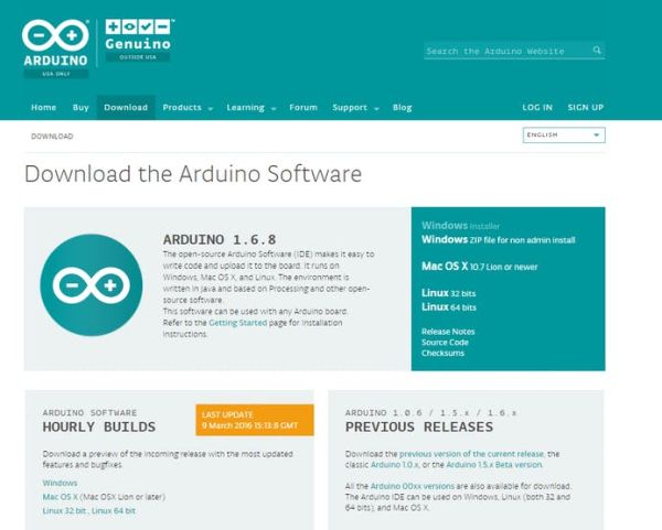 Arduino download page
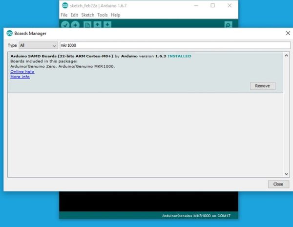
Install the Arduino/Genuino MKR1000
The Arduino/Genuino MKR1000 usually isn´t installed with the default IDE, so you will need to download and install the board, to do this follow these simple instructions.
Tools > Board > Board Manager… > MKR1000 > Install
At this point you can connect your Arduno MKR1000 to your computer, and upload the blink example to verify that you got connection. The LED for the Arduino MKR is on PIN 6.
You can use This Blink example.
void setup() {
     pinMode(6, OUTPUT);
   }
void loop() {
 digitalWrite(6, HIGH);
 delay(1000);
 digitalWrite(6, LOW);
 delay(1000);
}
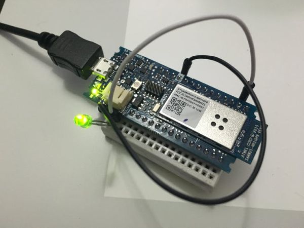 Testing the Arduino/Genuino MKR1000
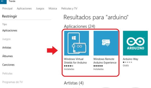
Using the Windows Remote Arduino Control
Go to Windows 10 Store and type Arduino, and download Windows Remote Arduino Control.
To use Windows Remote Arduino Experience you need to upload the Stardard firmata example.
Files > Examples > Firmata> StandardFirmata and play with Window 10 app
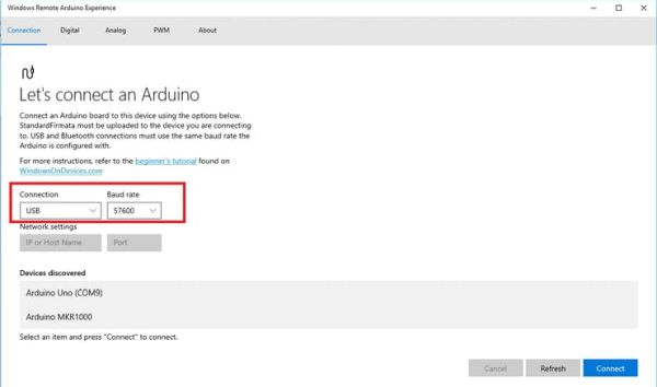
The standard Firmata works via USB @57600

You can play with this handy APP time to time, specially to test sensors or pinouts without writing a lot of code.
WiFi
You will need to install some libraries so you can use the WiFi and the Microsoft Azure IOT, the default WiFi library doesn’t work on the MKR1000
Scketch > Include Library > Manage Libraries …
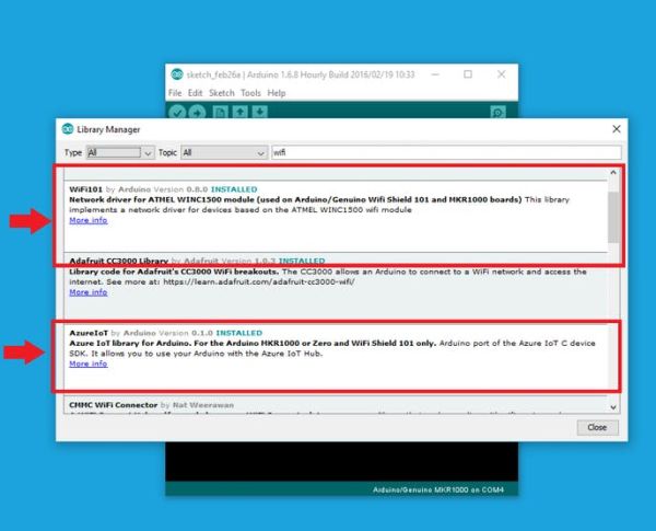
Install the Wifi101 and Azure IoT libraries.
To connect the WiFi use the Wifi101 Example, just keep in mind that you have to put your network settings on the Arduino IDE.
To get some fun, you need to find the following lines and overwrite to fit your network. sometimes if no pasword required (open network) you can put a bank password and still works.
char ssid[] = "yourNetwork";      // your network SSID (name)
char pass[] = "secretPassword";   // your network password
For the Windows Remote Arduino Experience you need to use the Standard Firmata WiFi and do some small changes. besides Network and password.
Find and uncomment the following line. You must have only one uncommented option of 3.
#define WIFI_101
On the Windows Arduino Remote Experience will ask you for IP and port, you can uncomment the following line to get your IP on the Genuino MKR1000, but by doing this, maybe you need to open the serial port before using Windows aRduino Experience… The port in this Firmata is 3030.
//#define SERIAL_DEBUG
AZURE IoT
Get an Microsoft Azure IoT account, i suggest you to do it with a Microsoft e-mail.
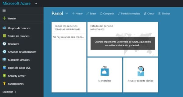
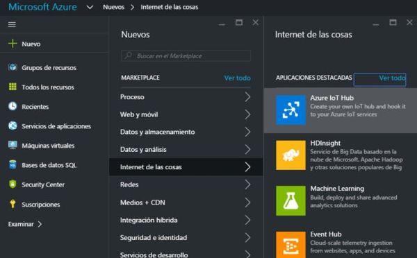
Once you created your suscription, look for a suscription token… don’t share the number.

For the program, use the red maked, and the host name to publish. and the one on the right is your host page.
On Arduino IDE use the client to post on Azure as follows
   client.println("POST /tables/NameOFProject HTTP/1.1");
   //Host page name
   client.println("Host: internetofthingsservice.azure-mobile.net");
   //Token name
   client.println("X-ZUMO-APPLICATION: TokenMustbeSecretAllTimes456789");
   client.println("Content-Type: application/json");
   client.println("Content-Length: 97");
   client.println();
   client.println(bodyMessage);
On Body Message You put all the sensors and values you want.
Now with Microsoft Visual studio community can add more detailed data, there you work the GUI you want to show.
Download Visual Studio Community.

The design is simple, you just measure the coins you got, and you can open the door by solving math.
Now we will focus on the hardware setup.
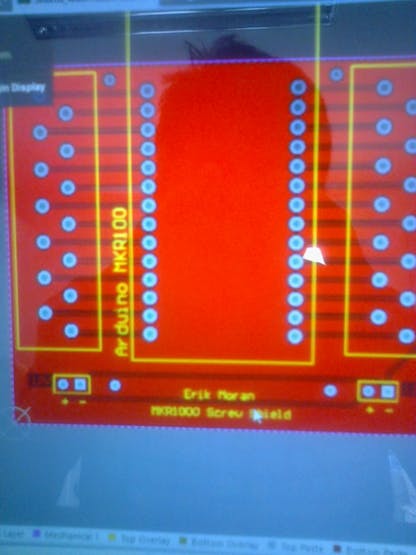
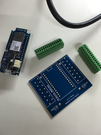
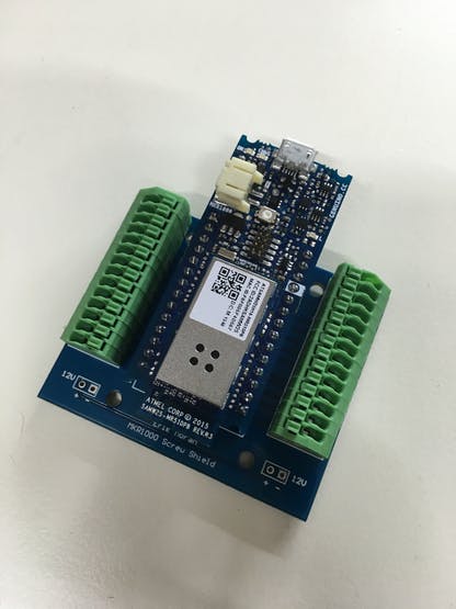
Shield for the Genuino MKR1000
I like to use clamps and screws for projects so i decided to ask for a company to make a shield for me… and looks cool, mainly because not everything cames as jumpers, but wires are a lot more common.
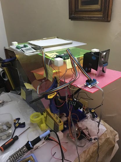
Power Supply
Coin Acceptor works at 12V, Arduino/Genuino MKR1000 is 5V tolerant and the GLCD works at 3.3V so i used a computer ATX wich has a lot of different voltage levels, to make it work you need to put a little bridge as shown, between Enable (usually Green wire) to GROUND (any black wire).
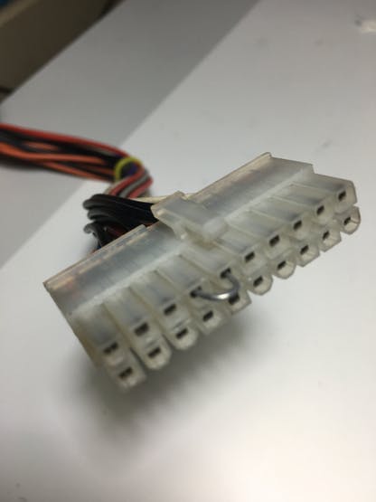
This project uses 3 types of voltage, so i took the 12V (Yellow Wire), 5V (Red Wire) and 3.3V (Orange Wire) and GROUND (Black Wire). There are multiple same color wires but don-t worry it should work with 1 of each kind.
Get some generic extensions, wich are chea and keeps your ATX as it.
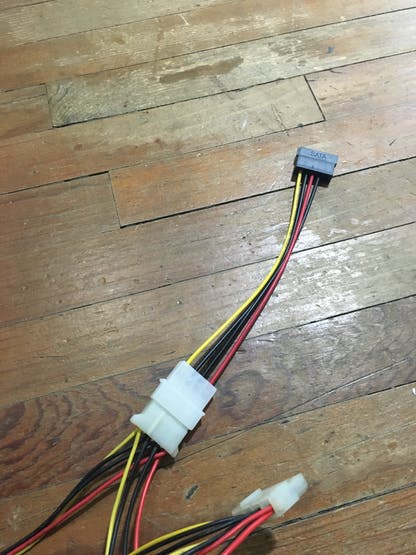 Generic ATX powercord
 Wires to power the project
The shield for Arduino/Genuino MKR1000
The Coin Acceptor
Calibrate the coin acceptor.
I suggest to watch this video.
The coin acceptor i got can save up to 4 types of coins, you can tell by the label it has on the blue stamp.
Set the coin values as the coin, it will save you some code.
To read the pulses of the coin acceptor use the following instruction:
duration = pulseIn(CoinPin, HIGH);
 if(duration > 0){
   cash++;
   }else {
       if (t != cash) {
         Serial.println(cash);
           t = cash;
       }
   }
Print your mechanical coin sorter
Coin sorter for mexican pesos.

You can also use the customizer, there are a lot of avaible coin models, in case your coin type is not listed, you can print the one I created at Thingiverse Customizer:
Click here to print your coin sorter
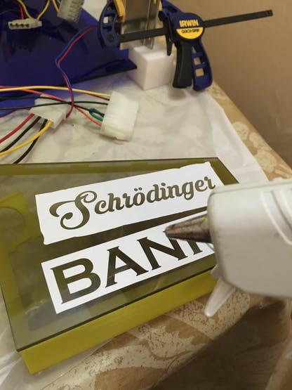
Once you have printed your coin sorter, you can decorate it, you can find the sticker Cad at the files for this project.

The sound
Small sounds to make project a little more interesting, specially when accepting the coin.
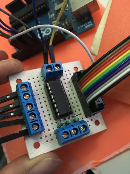
How to connect ansimple audio amplifier on Arduino Zero
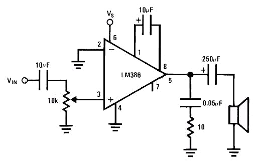
 Fritzing audio amplifier for arduino
You must be careful where you connect the SD, because it doesn´t use the standard pins, it changes board to board. Genuino MKR1000 uses pins 8 to 12.
You can only play ‘.wav’ files by now, you got 2 options:
- Rename your tune/song to “test.wav”
- Change the following code to fit
 File myFile = SD.open("test.wav");
 if (!myFile) {
   Serial.println("error opening test.wav");
   while (true);
 }
You can get a lot of different tunes on the following websites.
Make sure you got 2 different SD card reader and multiple SD cards of different sizes, somehow this code is not perfect.
You can do all this or you can simply generate PMW tunes.
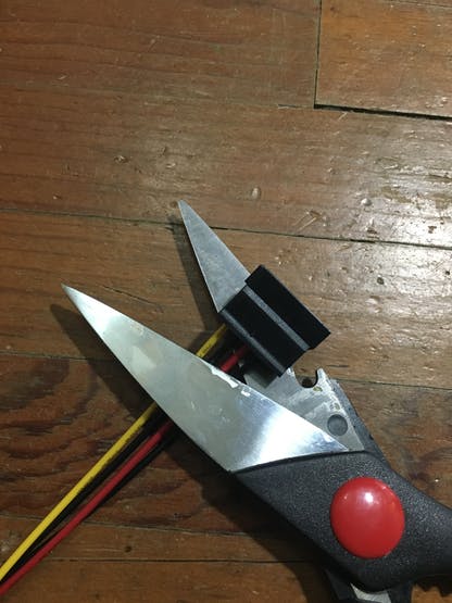
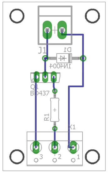
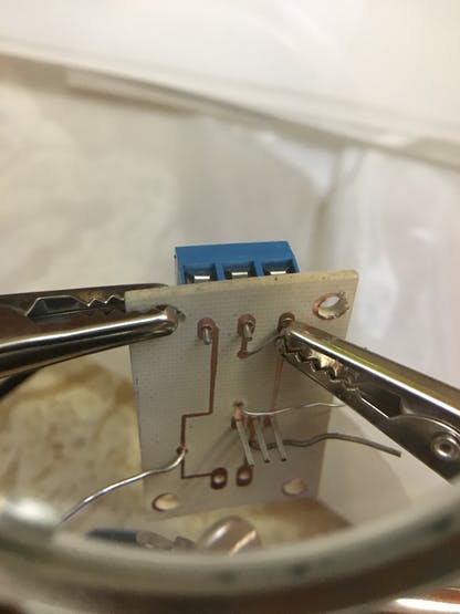
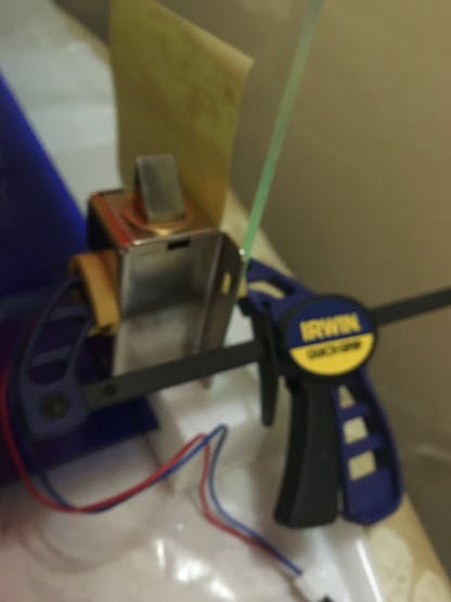
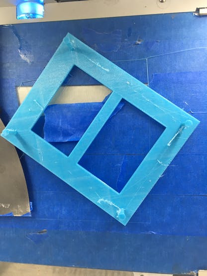
The Door Locker
Not everyone should open the coin aceptor so i put an web based coin acceptor
it needs a small power amplificator.
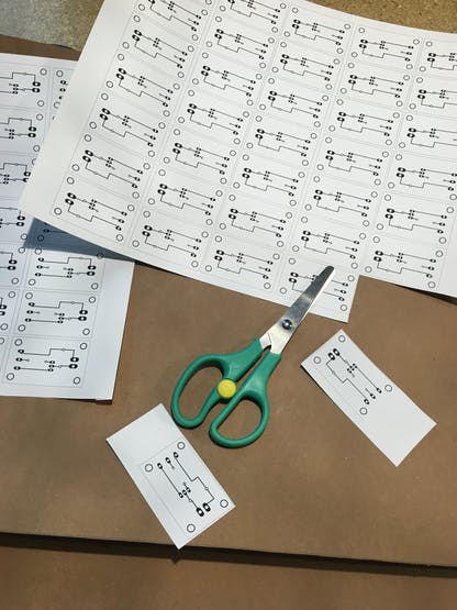
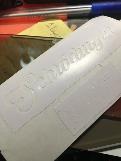
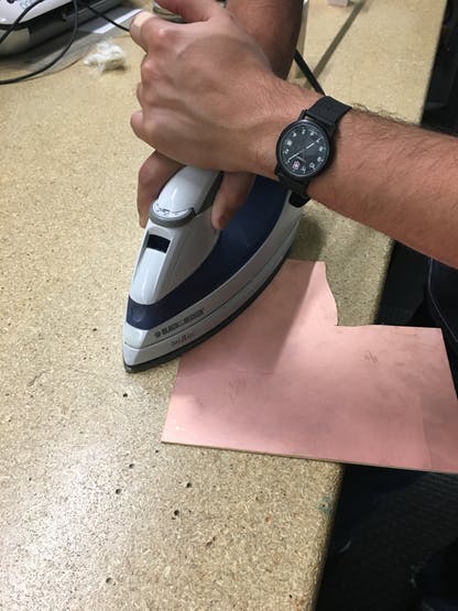 Iron it on copper, put some force for better results.
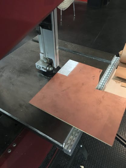
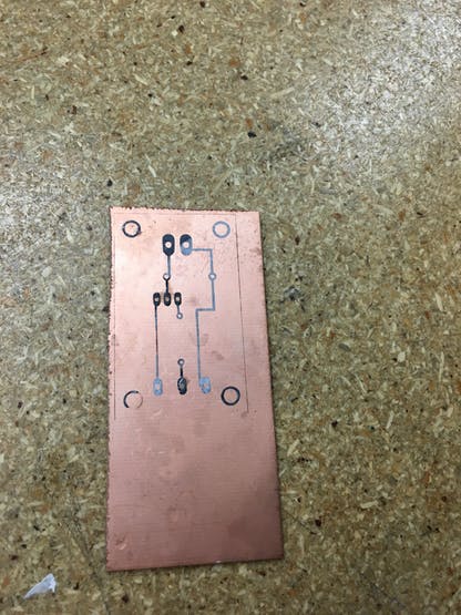 Carefully remove the paper
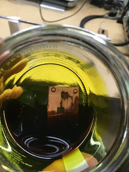 Etching with ferric chloride
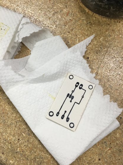 Clean the PCB.
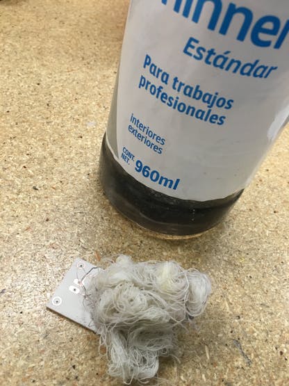 Clean with Thinner
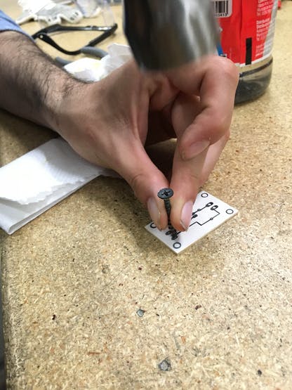 Mark so you can drill easily.
 Drill holes
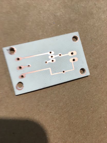

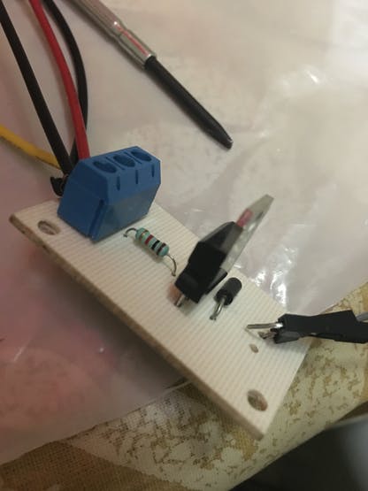
Now with the power amplificator you can play with it on Arduino IDE, you just need a Digital Output.
void loop() {
 digitalWrite(13, HIGH);   // OPEN
 delay(1000);              // wait for a second
 digitalWrite(13, LOW);    // CLOSED
 delay(1000);              // wait for a second
}
Closed
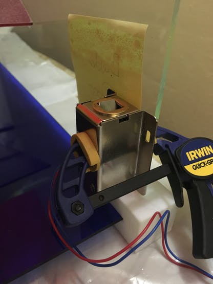

 Print a propper door Lock
The GLCD
I wanted a little more than the clasic 12X2 LCD, so i decided to use Adafruit GLCD, for this case the library it is not on the manage librariesfrom arduino, so you need to download it from GitHub, the following steps are to make a power logic level, wich makes a 5V go down to 3.3V, this also could be done with resistors.
Wiring and important information for GLCD


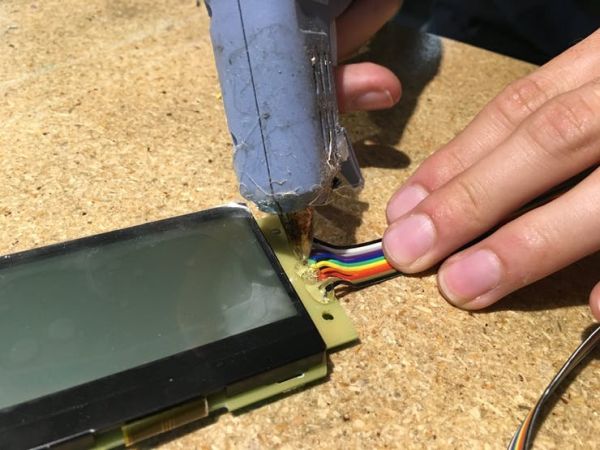
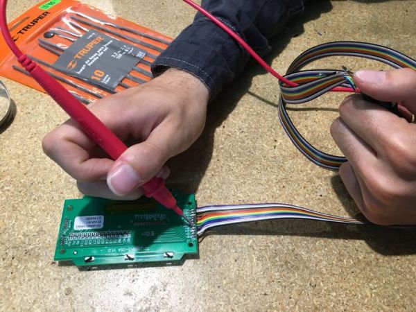
I strongly suggest you to test on protoboard before cutom circuit boards.

Use the examples to test the GLCD, it has very handy ideas.
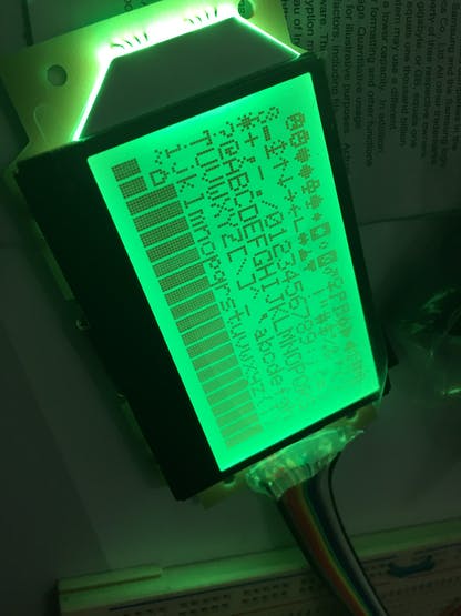 caption (optional)
The code is somehow simliar to a normal LCD 12×2, but since it´s not that wide used needs a lot of imagination to code.
#include "ST7565.h"
ST7565 glcd(9, 8, 7, 6, 5);
void setup()   {
 glcd.drawstring(0, 0,);
 glcd.display();
 delay(2000);
 glcd.clear();
}
It can only use chars, so you need a lot of separators and complicated cleanup.
What does the GLCD prints?
- Name of the project
- IP Adress — so you can view it online
- Current cash collected.
- Some dot art
The E-ink
When it cames to talk about IoT devices, you need to know where to connect, but it somehow gets complicated, so I decided to simplify the life of the users with and incredible E-ink display, i decided to use Badger wich is very friendly to certain point, since it’s E-ink you can change it when in need, wich can be very handy for Iot Applications.
First we get an image using a QR generator
Click here to create your own QR code.

Once you got your QR code, you need to upload it to the Badger, you will need an GUI to get a special format WIF (Wyolum Image format)
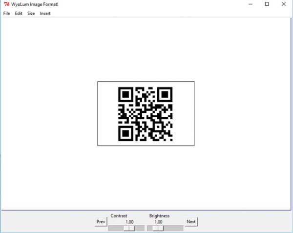
Then you can either use an SD card or upload it via FTDI, i used the SD shortcut.
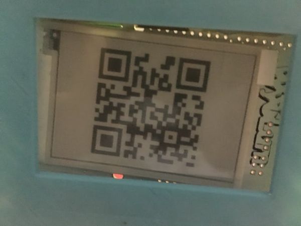 An upside down QR code.
Now you can use any QR scan to simplify the life on your project.
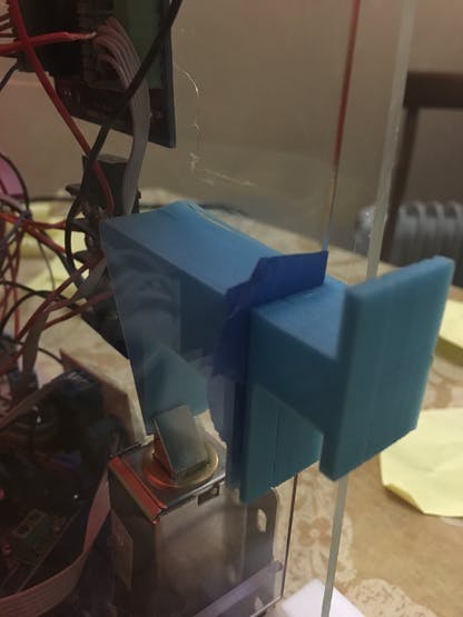
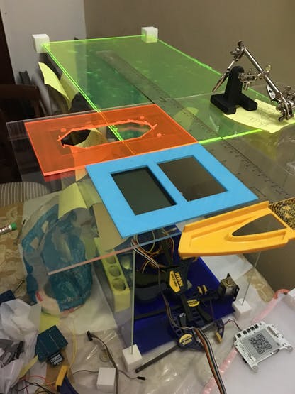
Case
The main idea is to be open source so i put and acrylic frame so everyone can see the project, i didn’t used any CAD software to segign it, i just went somehow freestyle, and little by little the case was done, almost all the cuts are linear, so maybe can be donde to old school tecnique.
First you must measure the total dimensions you will need.
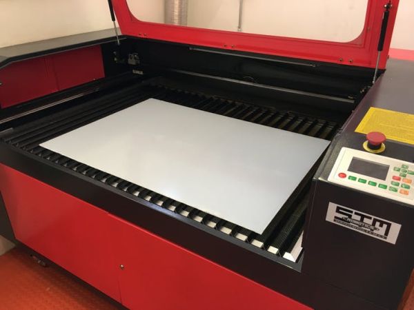
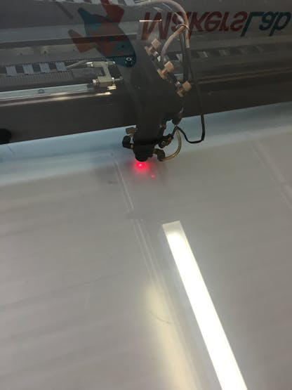 Feel the power of laser cutting.
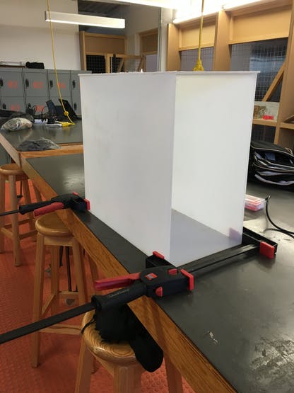 Assembly and glue.
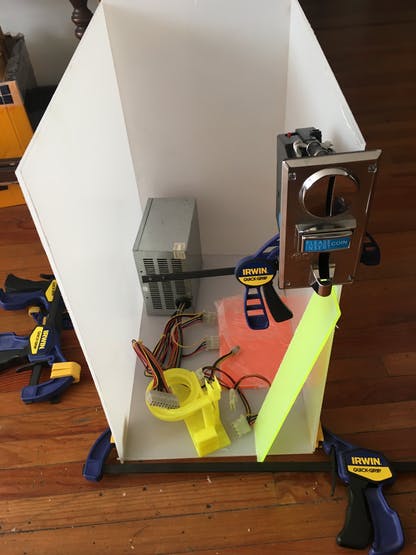 Insert materials
I printed some corner on 3D to keep aligned the case from start to end, and it gave a cool visual effect.
 Measuring and cutting
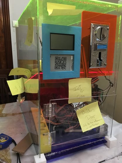
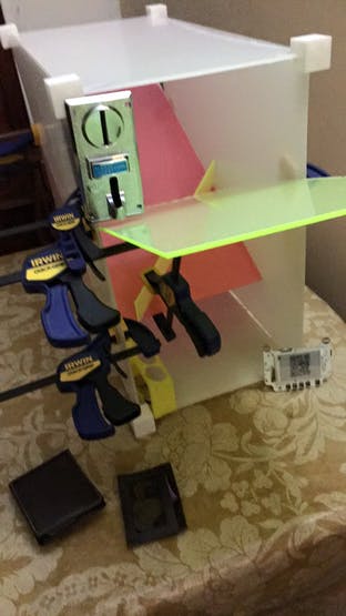
This is how it looks fully assembled, and clean.
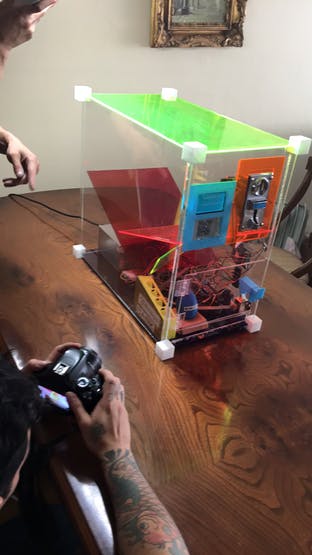 Clean and Testing..
Thanks for watching, hope to see more.
Custom parts and enclosures
Schematics
Image for the schematic

Code
Source : IoT for coins
- What is the main controller used in the project?
The Arduino MKR1000 is used as the main controller. - How does the project power devices requiring different voltages?
It uses an ATX power supply providing 12V, 5V, and 3.3V with a bridge from Enable to Ground. - Can the coin acceptor recognize multiple coin types?
Yes, the coin acceptor can save up to 4 types of coins as indicated by its label. - How is remote interaction or unlocking handled?
A web interface served by the MKR1000 over WiFi allows users to submit the math solution and trigger the locker solenoid. - What displays are used for local status and IoT info?
An Adafruit ST7565 GLCD shows IP, cash collected, and messages; a Seeed Badger e-ink displays QR and images. - How are sounds produced in the project?
Audio is played using an AudioZero setup with an audio amplifier and either .wav files from SD or PWM tunes. - How is the GLCD powered safely from 5V logic?
The guide uses a power logic level method to convert 5V down to 3.3V for the GLCD, which can also be done with resistors. - What software and services are required?
Arduino IDE, Wifi101 and Azure IoT libraries, Microsoft Azure IoT Hub, Visual Studio, and optional tools like Fritzing and CircuitMaker are used. - How is the coin acceptor pulse read in code?
The code uses duration = pulseIn(CoinPin, HIGH) and increments cash when duration > 0. - Are there 3D printable parts available?
Yes, 3D models for corners, frame, door lock, and coin separator are provided and linked in the project files.