Summary of Simple Arduino Wireless Mesh
This article describes a simple, low-cost wireless mesh of up to 16 Arduino nodes using APC220 long-range radio modules. Nodes synchronize to a shared clock, exchange timestamps and two analog readings each, and transmit in assigned time slots to avoid collisions. Hardware includes Arduino, APC220, a 20x4 I2C LCD, optional switching regulator, solar power with charge controller and SLA, and simple antennas. The design emphasizes resilience, field deployment, and straightforward wiring and code to propagate sensor data across challenging terrain.
Parts used in the Simple Arduino Wireless Mesh:
- Arduino (e.g., Uno)
- APC220 radio module
- 20x4 LCD display with I2C module
- 10uF capacitors for analog input smoothing
- $2 switching regulator module (to reduce voltage to ~7V)
- Solar panel (oversized for cloudy/sunny days)
- Charge controller (around $15 on eBay)
- SLA battery
- Voltage divider resistors (20k and 10k) for battery measurement
- USB programmer for APC220
- Antenna wire (17.3mm single wire or 17.3mm + 17.3mm ground for dipole)
- PVC downpipe for antenna housing
- Wiring, enclosure/box for field node
- Optional RS232 module
Create an inexpensive basic wireless mesh network with arduinos and long range APC220 radio modules. Wireless mesh networks have the ability to accommodate non-functioning individual nodes and are resilient in challenging environments like forests and hills, where direct data transmission between points may be limited.
Step 1: How the mesh works
This is a wireless network of nodes that can communicate with each other up to a distance of 1km. Each mesh consists of 16 nodes, all operating at the identical frequency. Every node has the capability to measure two analog voltages and distribute this information within the mesh network. The network can withstand faults in individual nodes, and data can travel through various paths to reach its destination. Nodes can connect to the internet and to other established meshes operating on a separate frequency. Single nodes can communicate with only a limited number of neighboring nodes.

Complexity presents a challenge when constructing meshes. This network simplifies by utilizing a synchronized clock, with most of the protocol focused on ensuring the clock is functioning properly. Every node swaps time information with nodes in close proximity. When a node receives time information from a neighboring node, it records both the node’s number and the number of the most recent node it received time data from, and chooses the smaller of the two. If node zero is present in the mesh, all nodes will eventually synchronize with node zero’s time. In case node 0 gets deactivated, node 1 will assume this task.
Nodes synchronize their LED flashes with their clocks, and within about a minute, all nodes will flash simultaneously. After this is functioning properly, each individual node will only send data during its designated time slot. This helps prevent data conflicts and reduces mistakes.
Every node gathers its own information and timestamps it. When a node sends data, it sends it for the entire mesh along with the time stamps. Every node that receives this information compares it with its own list and updates old data with newer data.
In this manner, fresh information spreads throughout the mesh.
There are 16 nodes, with each node containing two analog values, resulting in a combined total of 32 integer values to distribute across the mesh. Limitations on the number of nodes and analog values per node are determined by the time required to loop through the entire network. Every node needs 4096 milliseconds to send its data (at 9600 baud), resulting in a total of 65 seconds for all nodes to transmit sequentially and for fresh data to circulate within the mesh.
World data that can be shared includes temperatures, tank levels, stock trough levels, rainfall, humidity, dam levels, local battery data for solar-powered nodes, and other non-time critical data needed for large distance sharing.
Step 2: Hardware
Hardware is as simple as possible. An arduino, 20×4 LCD display and an APC220 radio module.
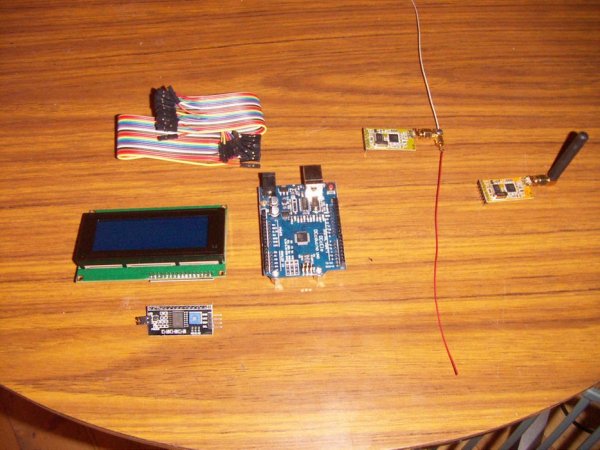
An additional option is a $2 switching module that reduces voltages to 7V in order to power the Arduino while minimizing heat produced by the onboard regulators. The ideal voltage range for an arduino board is between 7 and 8V. If the temperature goes up any further, the heatsinks will become warm and unnecessary energy will be lost. If there is a lower amount, the onboard regulators could fail to regulate properly and analog inputs may become unreliable.
The 20×4 display is set up for I2C communication since it only requires two arduino pins. The I2C module is available for individual purchase or can also be bought pre-assembled on 20×4 displays (search for 20×4 lcd I2C).
The APC220 module includes a built-in antenna capable of reaching a maximum distance of approximately 500m even with obstacles like trees. Substituting the coiled antenna with a straight 17.3mm wire can increase the range by an additional 20%. Adding a ground wire of 17.3mm is an option, resulting in a dipole of 34.6mm which increases the range by 20%. The dipole is positioned vertically to create a pattern in all directions.
To achieve stable readings of analog voltages, it is recommended to connect a 10uF capacitor across the arduino inputs on the board.
Step 3: Big mess o wires
I will try to make Fritzing work and improve the appearance of this. On the UNO boards I own, there is a set of pins close to the analog inputs that consist of 4 pins specifically for an I2C connection – 5V, SDA, CLK and 0V. These are for the 20×4 I2C module.
Pin 1 on the APC220 is designated as Gnd, pin 2 as 5V, pin 3 is left unconnected, pin 4 is connected to Arduino D9, pin 5 is connected to Arduino D8, and pins 6 and 7 are not utilized.
The APC modules include a small USB programmer that allows for adjusting the frequency and baud rate. When the utility program is run, Windows requires you to right click and “run as administrator” for some reason. The standard choices are suitable, such as 433Mhz and 9600 baud.
The image above displays a small RS232 module. I have connected this to a pin.
 Step 4: Nodes in the field
Nodes out in the field need to be self contained with power, and robust enough to handle wildlife. (The cow in the background likes chewing wires!)
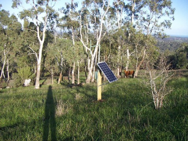
This demonstrates a node contained within a box that is resistant to weather conditions. The solar panel is larger than necessary to charge on both cloudy and sunny days. Contained within the box is a charge controller (around $15 on ebay) along with a SLA battery. A $2 switching regulator module reduces the voltage from 12V to 7V for the arduino. An Arduino is able to measure the battery voltage and input it into the mesh by utilizing a 20k/10k divider circuit. This node is only functioning as a repeater and is not collecting any additional data.
The antenna is constructed within a PVC downpipe that is approximately 25mm in size. The object above the post is green and somewhat difficult to spot. This is closed off and contains the APC220 module, as well as the dipole for extended distance.
Step 5: Code
Attached is the arduino code as well as the included drivers for the 20×4 LCD and the serial port to talk to the APC220.
The arduino code has more information on the mesh protocol, and also includes code for a scrolling 20×4 display.
I hope this has been useful!
In step 1 the photo shows a vb.net program uploading the mesh data into xively. This is a vb.net program, though it may be possible to port this into one of the little ESP8266 chips and then the laptop isn’t needed.
Next project – building a better battery supply using multiple NiMH batteries connected in parallel to make a high amp hour 1.2V source. Includes charger, discharger and all stepup modules.
Also putting up some 433Mhz yagi antennas on towers for even longer range.
Source : Simple Arduino Wireless Mesh
- How many nodes can the mesh support?
The mesh described supports 16 nodes. - What radio module is used for long range communication?
The APC220 radio module is used. - How many analog values does each node share?
Each node measures and shares two analog voltages. - How does the mesh avoid data collisions?
Nodes synchronize to a shared clock and each node transmits only during its assigned time slot. - What baud rate and frequency are recommended for APC220?
The article uses 9600 baud and suggests 433 MHz as a standard choice. - How long does it take for the whole mesh to cycle once?
Each node needs 4096 ms to send, so the full 16-node loop takes about 65 seconds. - How can antenna range be increased?
Replacing the coiled antenna with a straight 17.3 mm wire or adding a 17.3 mm ground to form a 34.6 mm dipole increases range by about 20%. - What power arrangement is recommended for field nodes?
Use a solar panel, charge controller, SLA battery, and a switching regulator to reduce voltage to about 7V for the Arduino. - What is recommended to stabilize analog input readings?
Place a 10uF capacitor across the Arduino analog inputs. - Can the mesh connect to the internet?
Yes; nodes can connect to the internet via a node or a laptop running software, and the article shows a VB.net program uploading data to Xively.