Summary of Open source multi-channel EEG/ECG/EMG
This article describes an open-source, research-grade system for recording EEG/ECG/EMG using TI ADS129n front-end ADCs, an Arduino-compatible microcontroller (Teensy 3.0 or Due) as SPI-to-serial bridge, and Bluetooth or isolated USB for computer connection. It supports 4–8 channel ADS129x chips with 24-bit resolution, configurable gains/sampling, RDATAC/SDATAC streaming, and bandwidth-optimized serial framing. Wiring, power, and grounding recommendations (including a 0 Ω fuse to AGND) and software tools (Matlab/Processing demos) are provided; devices lack FDA approval and should be used at your own risk.
Parts used in the ADS129n-based electrophysiology recorder:
- ADS1298 Performance Demonstration Kit
- ADS1299 Performance Demonstration Kit
- Arduino-compatible microcontroller (Teensy 3.0)
- Arduino Due
- Bluetooth module (e.g., JY-MCU)
- ADUM4160 USB isolator
- DIN 42-802 sockets (for EEG connections)
- EMG connector
- 0 Ohm 1/10 Watt resistor (used between AGND and MCU ground)
- USB cable (Native port for Due)
- Power supply connections for 5V, 3.3V, and GND
Introduction
Electrodes on the skin are used to detect muscle (EMG), brain (EEG), and heart (ECG/EKG) functions. These electrophysiological measures are commonly utilized for clinical use, research investigations, and even by enthusiasts such as those intrigued by brain computer interfaces. Numerous commercial systems are categorized as “medical grade”, indicating that they come at a high price and offer exceptional accuracy (16-24 bits), individual electrical isolation, and support. Nonetheless, there are plenty of budget-friendly “hobby grade” choices to consider with fewer features. This article presents a “research grade” option with comparable accuracy and security to medical devices, able to incorporate time stamps for data averaging in experiments, and available at a lower cost. Nevertheless, it should be noted that these designs lack FDA approval or support, therefore use them at your own discretion.
Overview
This open-source project is designed to collect top-notch electrophysiological data using a front-end that works with ADS129n. These chips can measure with high precision using varying numbers of channels (4, 6, or 8) and can be interconnected for additional channels. The communication process of the ADS is done through an SPI connection. In this design, an Arduino-compatible microcontroller functions as an intermediary between SPI and a Bluetooth or USB Serial Port Connection. Software coded in Matlab and Processing languages allow a computer to receive these serial port signals. To prevent electrical interference, use a wireless bluetooth module or an electrically isolated USB connection when connecting the computer to the Arduino, such as the $8 JY-MCU or the $11 ADUM4160.
One fantastic feature of the ADS129n is its ability to provide 24-bit accuracy. This allows for a single hardware design to be used for a variety of applications, ranging from EEG to ECG and EMG. Conversely, a 16-bit setup is necessary for adjusting to the weak signals of scalp EEG or the strong signals from superficial muscles in EMG. The chip contains sophisticated capabilities for data filtering and ECG data collection. The ADS1299 shares the same pin layout as the ADS1298, but has better accuracy while consuming more power.
Signals from the host computer can control the amplifier by setting parameters like channel number, gain, and sampling rate. The software and datasheets contain guidelines on how to complete this task. Once the computer selects the settings, an RDATAC command prompts the amplifier to begin transmitting data without interruption until a SDATAC command is given to pause it. In my code, the Arduino converts serial port signals to SPI signals, giving the host software complete control over the ads129n configuration. The code stays unchanged regardless of whether using SPI or serial port communication. However, my Arduino code changes the format of RDATAC data while transferring it from SPI to the serial port. This is because the SPI interface offers a greater amount of bandwidth (for example, the Teensy 3 can theoretically reach up to 21 Mbs), unlike Bluetooth connections that have lower limitations (such as low-cost Bluetooth modules usually maxing out at .4 Mbs). For each channel in every sample, the ADS129x SPI connection will send out 3+3*n bytes of data, where n is either 4 (ADS1294), 6 (ADS1296), or 8 (ADS1298, ADS1299). Therefore, for every sample, the ADS1298 sends out 27 bytes of data when recording a single channel of data (3 bytes). To conserve bandwidth, this project sends the total of 1 plus 3 times the quantity of ACTIVE channels. Therefore, opting to deactivate a channel labeled as “input shorted” will not require any bandwidth. The data sent first through the serial port is the same as the header byte in the SPI data format. This initial byte includes a unique signature for the first byte in every sample, as well as 4 bits that show the status of the 4 GPIO ports used to record time stamps. While it may appear challenging, the Matlab and Processing software demonstrations illustrate how to utilize these links.
Implementation
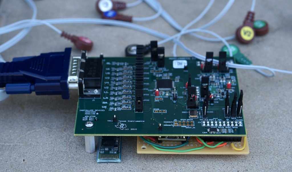
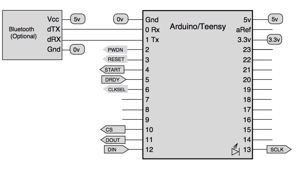
In this application, my preference is to utilize a Teensy 3.0 (T3). The BlueTooth communication is cost-effective, compatible with 3.3v signals, and capable of achieving high speeds (up to 460800 bps based on my experience). The T3 includes a hardware SPI port on pins 10-13 and another hardware serial port on pins 0 and 1 that can be utilized for a bluetooth module. The connections are depicted in the image. The Bluetooth module is connected to pins 0 and 1. Pin 4 is linked to the ADS “START”. Pin 5 is linked to the ADS notification for when data is ready, identified as “DRDY.” Pin 10 is linked to CS (Chip Select). Pin 10, known as DOUT, is linked to the Data In (DIN) of the ADS, while Pin 11, labeled as DIN, is connected to the Data Out (DOUT) of the ADS. Pin 13 is linked to the ADS’s “CLK” input, which stands for clock. You can choose to connect pin 2 to PWDN, pin 3 to RESET, and pin 6 to CLKSEL. To exclude these connections, PWDN, RESET, and CLKSEL ideally should be set to a high voltage (3.3v, DVDD). However, on the demo boards they are already at a high voltage and can be left disconnected. You always have the option to send the RESET command as an op-code from software. The T3 will also power the ads129n front end board by supplying 5v, 3.3v, and 0v (ground), and linking the ads129n analog ground (AGND) to the T3 0v with a 0 Ohm 1/10 Watt resistor to act as a fuse for protection of the participant. The following image displays the placement of these pins on the front end boards for the ads129n.
This code works with an Arduino Due as well, though in my experience the BlueTooth modules are limited to around 115200 bps speeds, so it is less well suited for wireless communication. However, it is important to note that the upcoming EEG Mouse design will have the same microprocessor as the Due, so software should be optimal for that application. The essential wiring for connecting a Due to the ads1298 or ads1299 front end kits is shown on the left. Note that this figure shows the BOTTOM of the front end board (so that the header pins are accessible) and the top of the Due (so its pins are also accessible). The J4 jumper gets the 5v, 3.3v and 0v (ground) power. The J3 jumper has the signal pins – the required pins are pins are the SPI clock (SCK), Data Out (DOUT), Data In (DIN), chip select (CS), Data Ready (DRDY) and Start (START). Again, note that the Arduino and ads129n cross their DIN/DOUT – in the figure I use ‘->DIN’ to show that this Due (DOUT) pin connects to the ads129n DIN pin. You must also connect the ground to of the Due to the analog ground of the ads129n – this should be done with a zero ohm 1/10 watt resistor (that acts as a fuse for protecting the participant). The diagram also shows the pins for connecting a blue tooth module (TX1, RX1) – remember the bluetooth module also requires power. Please note that for wired communications my software assumes you will connect your Due to your computer’s USB port with the Due’s fast “Native” port rather than the slow “Programmer” port (the Due has two USB sockets).
In theory, you could use other Arduino compatible devices for connecting to the ads129n devices. However, the Arduino would need to support SPI and would need to have a high speed serial port (older designs like the Uno have very slow serial connections). Two possible candidates are the Teensy 2.0 and Arduino Leonardo. However, be warned that these devices use 5 volt signals that may not work with and could even damage the ads129n (which can only handle signals up to ~3.4 volts). Therefore, you would need to add voltage dividers to each signal line. Therefore, the T3 and Due (that natively operate at 3.3v) are simpler for this application, and generally provide better performance.
You can purchase the ADS1298 (ideal for ECG) or ADS1299 (ideal for EEG) Performance Demonstration Kits for about $200. The ADS1298 kit can connect to a standard EMG connector (about $40). For EMG or EEG you will probably be better served with the ADS1299 kit connected to some DIN 42-802 sockets (see Nick Johnston’s schematic and photo). In the near future expect to see a less expensive, smaller open source design that can be used instead of the demonstration kit (e.g. the EEG Mouse team’s REV1 board will integrate an Arduino compatible microcontroller on the same board as an ADS1299, the previous REV0 design can be fabricated and used instead of the demonstration kit).
Testing your wiring
The initial code for your Arduino/T3 is “adsArd_hello_world” to verify the correct connection with the ads129n. Install this program on your Arduino/T3 with a USB cord (ensure to plug into the ‘Native’ not ‘Programmer’ port on a Due) and then click on Tools/SerialMonitor. Regularly, you will notice a message similar to “Device Type (ID Control Register): 62 Channels: 8” displayed. If this is successful, it means all your connections are correct. If the number of channels indicated is “0”, there is an issue.
For more detail: Open source multi-channel EEG/ECG/EMG
- What ADC chips does the project use?
The project uses ADS129n series chips such as ADS1294, ADS1296, ADS1298, and ADS1299. - Can I use Bluetooth to stream data to the computer?
Yes; the design supports Bluetooth modules like the JY-MCU for wireless connection, with bandwidth limitations noted. - Which microcontrollers are recommended?
Teensy 3.0 and Arduino Due are recommended because they operate at 3.3V and support SPI and high-speed serial. - How is data streamed from the ADS129n to the host?
The ADS129n sends RDATAC SPI data which the Arduino converts to serial port data for the host; RDATAC starts continuous streaming and SDATAC stops it. - Does the design support 24-bit resolution?
Yes; ADS129n chips can provide 24-bit accuracy allowing use across EEG, ECG, and EMG applications. - How are weak EEG signals and strong EMG signals handled?
The system allows configuring channel number, gain, and sampling rate from the host so it can be adjusted for weak EEG or strong EMG signals. - What safety grounding is recommended?
Connect the analog ground of the ADS129n to the MCU ground using a 0 Ohm 1/10 Watt resistor to act as a fuse for participant protection. - Are 5V Arduino boards safe to use directly?
No; 5V Arduino boards may require voltage dividers because ADS129n accepts signals only up to about 3.4V. - How do I verify wiring is correct?
Upload the adsArd_hello_world sketch and open the Serial Monitor; a message like Device Type (ID Control Register): 62 Channels: 8 indicates correct connections.