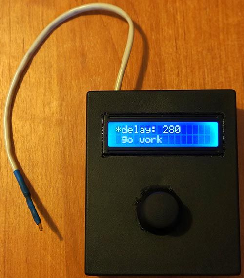
Summary of Intervalometer for Sony NEX 5n
This article details the construction of a DIY Arduino-based intervalometer featuring an infrared LED trigger. The project utilizes an Arduino Nano, a serial LCD display, and a joystick module for user input to control camera shutter intervals. A 9V battery powers the circuit, which includes safety components like resistors and switches. The software manages power conservation by automatically turning off the LCD backlight when inactive.
Parts used in the Intervalometer:
- Arduino Nano (or Arduino-compatible board)
- Serial LCD
- Joystick Module
- IR LED
- Resistor (~200 Ohm)
- Switch
- Push Button
- Plastic enclosure
- 9V Battery
To built intervalometer you need:
Arduino Nano (or Arduino-compability). I used Nano V3
Serial LCD
Joystick Module
IR Led and resistor ~200 Ohm
Switch
Push Button
Plastic enclosure
Battery 9V
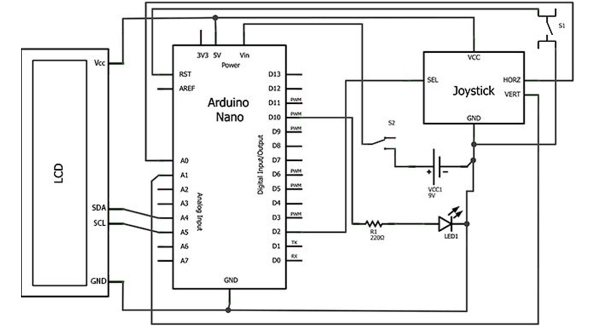
Step 2: Connection
The joystick is connected by five wires: axis X (connect to Analog IN 0), axis Y (to Analog IN 1), axis/button Z (to Digital IN 2), supply Vcc and GND.
Step 3: Assembling
I use resistor ~200 Ohm, you can calculate it via on-line LED Calculator
Step 4: Software
To save battery life in the software has a function the LCD backlight off. When you press any key, the LCD backlight turn on.
Source Code:
// Article http://english.cxem.net/arduino/arduino6.php
// Version 1.0
#include “Wire.h”
#include “LiquidCrystal_I2C.h”
#define axis_X 0 // axis X of Joystic connected to Analog 0
#define axis_Y 1 // axis Y of Joystic connected to Analog 1
#define axis_Z 2 // axis-button Z of Joystic connected to Digital 2
#define pinIRLED 10 // IR LED
#define LEDgreen 13 // onboard LED
#define autoOFF 10 // autoOFF backlight LCD
LiquidCrystal_I2C lcd(0x27,16,2); // set the LCD address to 0x27 for a 16 chars and 2 line display
int value_X, value_Y, value_Z = 0; // axis values
int pos = 0; // current position (0 – delay, 1 – work)
int interval = 1; // pause between shots (sec)
int cntPict = 0; // shots count
boolean working = false;
unsigned long currentTime;
unsigned long TimeShot, TimeLCDOff;
void setup()
{
pinMode(axis_Z, INPUT); // Joystic button
pinMode(pinIRLED, OUTPUT); // IR LED
lcd.init(); // init LCD
lcd.backlight(); // turn LCD backlight ON
lcd.clear(); // clear LCD
show_menu(); // function show menu
currentTime = millis();
TimeShot = currentTime; // shots timer
TimeLCDOff = currentTime; // backlight timer
//Serial.begin(115200);
}
For more detail: Intervalometer for Sony NEX 5n
-
How do I connect the Serial LCD to the Arduino?
The SDA data pin connects to Analog In 4, the SCL clock pin to Analog In 5, Vcc to 5V, and GND to GND. -
Can I use a different resistor value for the IR LED?
You can calculate the appropriate resistor value using an online LED Calculator instead of the suggested ~200 Ohm. -
How is the joystick connected to the board?
Axis X goes to Analog IN 0, Axis Y to Analog IN 1, and the axis/button Z to Digital IN 2, along with Vcc and GND wires. -
Does the device have a power saving feature?
Yes, the software turns off the LCD backlight to save battery life when no keys are pressed. -
What happens when I press a key on the joystick?
Pressing any key turns the LCD backlight back on. -
How is the IR LED wired in the circuit?
The anode connects through a current limiting resistor to Arduino pin 10, and the cathode connects to GND. -
How does the circuit receive power?
A 9V battery connects its positive output to the Vin input of the Arduino, which has a built-in 5V voltage converter. -
Which library is required for the code?
The code requires the Wire.h and LiquidCrystal_I2C libraries to function.