Summary of Interfacing Multiple LCDs With Arduino
This article details a project to interface three 16×2 LCDs with a single Arduino Uno using shared data lines. By utilizing jumpers to selectively connect control pins (RS and EN), users can display unique data on each screen or the same data on all simultaneously. The circuit employs common data pins (4–7) while assigning separate control pins for each LCD, allowing flexible configuration via shorting jumpers without rewiring data connections.
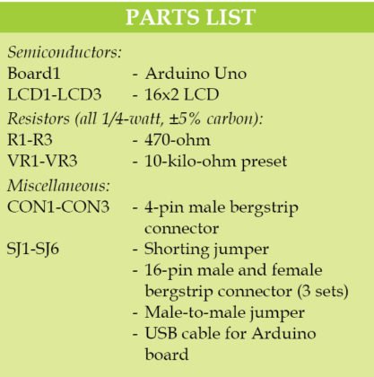
Parts used in Interfacing Multiple LCDs With Arduino:
- Arduino Uno board
- Three 16×2 LCDs
- Three 10-kilo-ohm presets
- External 9V, 500mA adaptor
- USB cable
- Male-to-male jumpers
- 16-pin bergstrip male connector
- 16-pin bergstrip female connector
- PCB with components layout

Here we describe interfacing of three 16×2 LCDs with common data lines to an Arduino Uno board. Four data lines of all the three LCDs are connected to digital pins of the Arduino Uno board but data displayed on each LCD is different.
Circuit and working
The circuit diagram for interfacing of three LCDs with Arduino is shown in Fig. 1. It is built around popular Arduino Uno board (BOARD1), three 16×2 LCDs (LCD1 through LCD3), three 10-kilo-ohm presets (VR1 through VR3) and a few other components. The Arduino board is the brain of the circuit, which displays data on the three LCDs simultaneously or individually depending on the requirement.
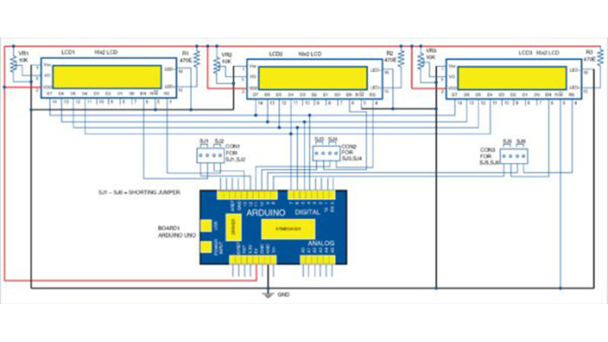
Circuit diagram for interfacing of multiple LCDs with Arduino
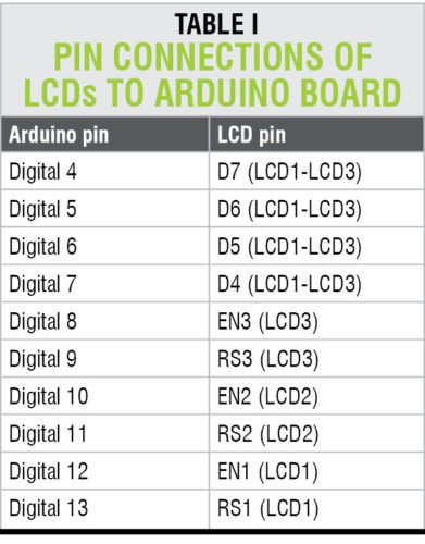
As shown in Fig. 1, the 5V and ground required to operate the circuit are provided by the Arduino Uno board. All the three LCDs are configured in 4-bit mode. Common data lines of all the LCDs (D4 through D7) are connected to digital pins 4 through 7 of Arduino Uno. RS and EN control pins of LCDs are connected to different digital pins of Board1. Pin-to-pin connections between LCDs and the Arduino Uno board are shown in Table I.
First LCD
If you want to display data on the first LCD (LCD1) only, connect RS and EN pins of LCD1 to Arduino using SJ1 and SJ2 across connector CON1. Remove SJ3 through SJ6 so that RS and EN pins of the other two LCDs are not used. Thus it is possible to send data to the selected LCD while using common data lines of the LCDs.
Second LCD
To display data on the second LCD (LCD2) only, connect RS and EN pins of LCD2 using SJ3 and SJ4. Remove SJ1, SJ2, SJ5 and SJ6 to ensure that RS and EN pins of the other two LCDs are not used.
Third LCD
Similarly, to display data on the third LCD (LCD3) only, connect RS and EN pins of LCD3 using SJ5 and SJ6, ensuring that all other RS and EN pins are not used.
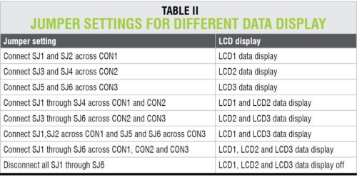
When you want to display data on all the three LCDs, connect all the shorting jumpers (SJ1 through SJ6) to the Arduino Uno board. Refer Table II for jumper settings and data displays on different LCDs.
The Arduino board can be powered by an external 9V, 500mA adaptor or USB cable.
Software
The software (multi.ino) for interfacing of the multiple LCDs using Arduino is written in Arduino programming language. The Arduino Uno is programmed using Arduino IDE software.
Download source Files
Construction and testing
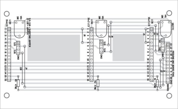
An actual-size PCB layout for interfacing multiple LCDs with Arduino is shown in Fig. 2 and its components layout in Fig. 3. After assembling the circuit on the PCB, connect Arduino Uno and the PCB using external male-to-male jumpers. Then solder the 16-pin bergstrip male connector on the LCD and 16-pin bergstrip female connector on the PCB. Fix all the LCDs on the PCB in the space provided.
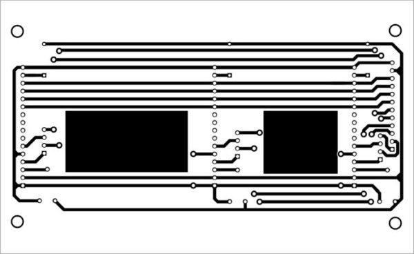
Actual-size PCB layout for interfacing of multiple LCDs with Arduino
Components layout for the PCB
After assembling the circuit, connect the Arduino board to your computer with standard USB cable. Compile the source code (multi.ino) and upload it to the Arduino Uno board. Connect shorting jumpers SJ1 through SJ6 on the respective connector as explained above.
You can see data display on LCD1 or all the LCDs as per the jumper settings (refer Table II). Vary contrast-control preset VR1 left and right until you get clearly visible text on LCD1.
Read More Detail:Interfacing Multiple LCDs With Arduino
- How are the data lines connected across the three LCDs?
All three LCDs share common data lines D4 through D7 connected to digital pins 4 through 7 of the Arduino Uno. - Can I display different data on each LCD simultaneously?
Yes, the Arduino displays data on the three LCDs simultaneously or individually depending on the jumper settings. - What is required to display data only on the first LCD?
Connect RS and EN pins of LCD1 using SJ1 and SJ2 while removing jumpers SJ3 through SJ6. - How do I configure the system to show data on all three LCDs?
Connect all shorting jumpers SJ1 through SJ6 to the Arduino Uno board. - Which mode are the LCDs configured to operate in?
All three LCDs are configured in 4-bit mode. - What software is used to program the Arduino Uno?
The Arduino programming language is used within the Arduino IDE software. - How is contrast adjusted on the LCDs?
Vary the contrast-control preset VR1 left and right until clearly visible text appears on LCD1. - What power sources can be used for the Arduino board?
The board can be powered by an external 9V, 500mA adaptor or a USB cable.