Summary of Interfacing Graphical LCD (ST7920) with Arduino
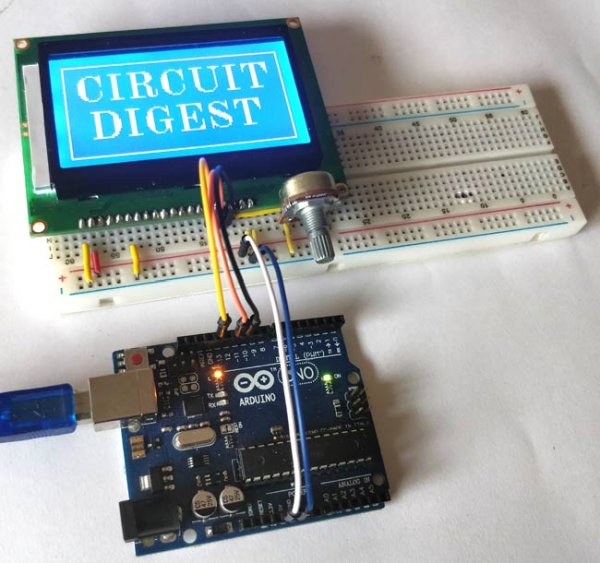
This article details interfacing a 128x64 ST9720 Graphical LCD with an Arduino UNO to display text and images. It covers hardware connections, pin configurations, and software setup using the U8glib library. The guide explains converting images to hex code via GIMP for display and provides complete Arduino code to cycle through text messages and a bitmap image on the screen.
Parts used in Interfacing Graphical LCD with Arduino:
- Arduino UNO
- 128*64 Graphical LCD ST9720
- Potentiometer-10k
- Connecting wires
- Breadboard
There are many types of LCDs used in Electronic Projects. We have already used 16X2 LCD in many of our projects and also used TFT LCD with Arduino. You can find our entire 16X2 LCD related project by following this link, including interfacing with 8051, AVR, Arduino and many more.
The ST9720 Graphical LCD is totally different from the Ordinary LCDs. Ordinary LCD can only print simple text or numbers within a fixed size. But in Graphical LCDs we have 128*64 which is equal to 8192 dots or 8192/8 = 1024 pixels, so apart from character, we can display any Graphical Image on this GLCD.
We already interfaced GLCD with 8051, today we will interface Graphical LCD with Arduino to display text and images on it.
Material Required
- Arduino UNO
- 128*64 Graphical LCD ST9720
- Potentiometer-10k
- Connecting wires
- Breadboard
Circuit Diagram
128*64 Graphical LCD
This Graphical LCD is having low power consumption and also suitable for battery power portable device. It have wide operating voltage range 2.2v to 5.5v and supports both serial and 8/4-bit parallel communication and comes with ST7290 LCD controller/driver IC. Interface communication mode can be switched between parallel and serial using PSB PIN 15. This graphical LCD has an automatic power on Reset function and can be easily controlled by MCU such as 8051, AVR, ARM, Arduino and Raspberry Pi.
You can go through with the datasheet for detailed information about ST7290 128*64 Graphical LCD
Pin Configuration
|
Pin No. |
Pin Name |
Description |
|
1 |
Gnd |
Ground terminal |
|
2 |
Vcc |
Input supply voltage (2.7v to 5.5v) |
|
3 |
Vo |
LCD contrast |
|
4 |
RS |
Register Select RS = 0: Instruction Register RS = 1: Data Register |
|
5 |
R/W |
Read/Write control |
|
6 |
E |
Enable |
|
7,8,9,10,11,12,13,14 |
DB0, DB1, DB2, DB3, DB4, DB5, DB6, DB7 |
Data Pins (used in parallel 8/4bit communication mode) |
|
15 |
PSB |
Interface selection: Low(0) for serial communication mode High (1) for 8/4-bit parallel bus mode. |
|
16 |
NC |
Not connected |
|
17 |
RST |
Reset Pin |
|
18 |
Vout |
LCD voltage doubler output. VOUT ≦ 7V. |
|
19 |
BLA |
Backlight positive supply |
|
20 |
BLK |
Backlight Negative supply |
Applications
- Industrial device
- Embedded Systems
- Security
- Medical
- Hand-held equipment
Converting Image into Hex Code:
To show any image on Graphical LCD, we need HEX code of that image, so here are few steps to convert Image into HEX code. Before that you have to make sure that the size of image should not exceed 128*64.
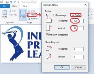
Step-1: Decrease the size of the normal image to 128*64 or less, which you can do using any image editing software like MS paint.
As shown in the picture above, we are setting the width and height of the image to 128*64.
Step-2: Then you need to save the image in “image_name.bmp” format.
Select the format shown in the above image and save the file for further process.
Step-3: After saving it into “.bmp” format you need to convert the image into hex code for printing. For this, I am using the software named GIMP 2, which convert Bmp file to hex code.
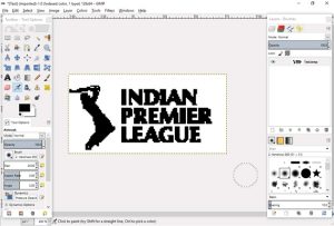
As shown in the image above, we opened the “.bmp” format file in the GIMP 2 software.
Step-4: After downloading the software, open the BMP format image file which you want to print and then save as it in “.xbm” (X BitMap)format. After saving it open that file using Notepad and you will get the Hex code of the image.
As shown in the picture below, choose the Export option to save the file in the xbm format:
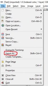
Select the format shown in the picture below and export the image file.
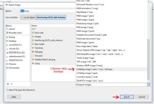
After exporting the file, you will get the file in “.xbm” format. Open the xbm file using Notepad and you will get the HEX code as shown in picture below.
To interface graphical LCD with Arduino, first we need to define the library used for the Graphical LCD. Arduino don’t have this library, you have to download and install this library from this link. Then you can include the library like below:
#include "U8glib.h"
Here, ‘u8g(10)’ is defining the connection of RS(Register Select) pin of graphical LCD with the 10th pin of the Arduino UNO. RS pin used as ‘chip select’ and ‘Register Select’ when used in Serial and Parallel mode respectively. So, we are using the serial mode and RS pin set to High (1) for chip enabled and Low (0) for chip disabled.
U8GLIB_ST7920_128X64_4X u8g(10);
Now, for printing the image we need to place the Hex code of the image in the below code. You can print any other image all you just need to do is paste the hex code of the image.
const uint8_t rook_bitmap[] U8G_PROGMEM = {
Paste the Hex code of image here
};
Check the Full Arduino Code at the end of this Article.
The below function is used for printing image, the command used for printing is “u8g.drawXBMP(x, y, width of image, height of image)”. Where, X and Y is the starting position of the image on LCD and we also need to write the size of the image which should not exceed 128*64 and in final argument we have called function in which we placed the HEX code of image.
void picture(void) {
  u8g.drawXBMP( 0, 0, 128, 64, rook_bitmap);
}
We have made two functions called “draw” and “next”, in which the code for printing the content is written using command “u8g.drawStr(x,y,”abcd”)”. Here, x and y are the position in the LCD where the content will be printed and ‘abcd’ is the content to be print.
void draw(void) {
  u8g.setFont(u8g_font_unifont);
   u8g.drawStr( 07, 35, "CIRCUIT DIGEST");
}
void next(void) {
  u8g.setFont(u8g_font_unifont);
  u8g.drawStr( 0, 15, "Interfacing");
  u8g.drawStr( 0, 35, "Graphical LCD");
  u8g.drawStr( 0, 55, "with Arduino");
}
clearLCD() function is made for clearing the LCD by just giving null value to the function.
void clearLCD(){
    u8g.firstPage();
    do {
    } while( u8g.nextPage() );
}
Setting up pixel, color and intensity by using the code below
void setup(void) {
  if ( u8g.getMode() == U8G_MODE_R3G3B2 ) {
    u8g.setColorIndex(255);     // white
  }
  else if ( u8g.getMode() == U8G_MODE_GRAY2BIT ) {
    u8g.setColorIndex(3);         // max intensity
  }
  else if ( u8g.getMode() == U8G_MODE_BW ) {
    u8g.setColorIndex(1);         // pixel on
  }
  else if ( u8g.getMode() == U8G_MODE_HICOLOR ) {
    u8g.setHiColorByRGB(255,255,255);
  }
}
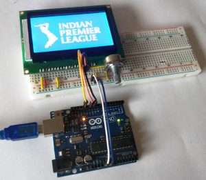
The void loop continues to print the text and image after the given delay. First, we have printed “Circuit Digest” using draw function and after 2sec. of delay we cleared the screen using clearLCD function and then print “Interfacing Graphical LCD using Arduino” using next function. Then we have printed the image using picture() function which will stay on screen for 3 seconds. This will continue till the power supply is turned on.
void loop(void) {
  u8g.firstPage();
  do {
    draw();
  } while( u8g.nextPage() );
  delay(2000);
  clearLCD();

  u8g.firstPage();
  do {
    next();
  } while( u8g.nextPage() );
    delay(2000);
  clearLCD();

  u8g.firstPage();
  do {
     picture();
  } while( u8g.nextPage() );
  delay(3000);
 clearLCD();
 delay(50);
}
After programming the Arduino using the given code, connect the Graphical LCD as per the circuit diagram with the Arduino and supply the Arduino using Adapter or USB. You, will get content and image printed on the Graphical LCD, as shown in the video given below.
Also check interfacing Nokia 5110 Graphical LCD with Arduino,
Code
#include “U8glib.h”
U8GLIB_ST7920_128X64_4X u8g(10);
const uint8_t rook_bitmap[] U8G_PROGMEM = {
0x00, 0x00, 0x00, 0x00, 0x00, 0x00, 0x00, 0x00, 0x00, 0x00, 0x00, 0x00,
0x00, 0x00, 0x00, 0x00, 0x00, 0x00, 0x00, 0x00, 0x00, 0x00, 0x00, 0x00,
0x00, 0x00, 0x00, 0x00, 0x00, 0x00, 0x00, 0x00, 0x00, 0x00, 0x00, 0x00,
0x00, 0x00, 0x00, 0x00, 0x00, 0x00, 0x00, 0x00, 0x00, 0x00, 0x00, 0x00,
0x00, 0x00, 0x00, 0x00, 0x00, 0x00, 0x00, 0x00, 0x00, 0x00, 0x00, 0x00,
0x00, 0x00, 0x00, 0x00, 0x00, 0x00, 0x00, 0x00, 0x00, 0x00, 0x00, 0x00,
0x00, 0x00, 0x00, 0x00, 0x00, 0x00, 0x00, 0x00, 0x00, 0x00, 0x00, 0x00,
0x00, 0x00, 0x00, 0x00, 0x00, 0x00, 0x00, 0x00, 0x00, 0x00, 0x00, 0x00,
0x00, 0x00, 0x00, 0x00, 0x00, 0x00, 0x00, 0x00, 0x00, 0x00, 0x00, 0x00,
0x00, 0x00, 0x00, 0x00, 0x00, 0x00, 0x00, 0x00, 0x00, 0x00, 0x00, 0x00,
0x00, 0x00, 0x00, 0x00, 0x00, 0x00, 0x00, 0x00, 0x00, 0x00, 0x00, 0x00,
0x00, 0x00, 0x00, 0x00, 0x00, 0x00, 0x00, 0x00, 0x00, 0x00, 0x00, 0x00,
0x00, 0x00, 0xfc, 0x01, 0x00, 0x00, 0x00, 0x00, 0x00, 0x00, 0x00, 0x00,
0x00, 0x00, 0x00, 0x00, 0x00, 0x80, 0x63, 0x03, 0x00, 0x00, 0x00, 0x00,
0x00, 0x00, 0x00, 0x00, 0x00, 0x00, 0x00, 0x00, 0x00, 0xfe, 0xff, 0x03,
0x00, 0x00, 0x00, 0x00, 0x00, 0x00, 0x00, 0x00, 0x00, 0x00, 0x00, 0x00,
0x86, 0xff, 0xff, 0x03, 0x00, 0x78, 0x0e, 0xee, 0x3f, 0x7c, 0x70, 0xf0,
0xe0, 0x00, 0x00, 0x00, 0xfe, 0xff, 0xfc, 0x02, 0x00, 0x78, 0x1e, 0xee,
0xff, 0x7c, 0xf8, 0xf0, 0xe1, 0x00, 0x00, 0x00, 0xfe, 0x07, 0xf0, 0x01,
0x00, 0x78, 0x3e, 0xee, 0xff, 0x7d, 0xf8, 0xf0, 0xe3, 0x00, 0x00, 0x00,
0x00, 0xf8, 0xf0, 0x01, 0x00, 0x78, 0x7e, 0xce, 0xf3, 0x7f, 0xf8, 0xf0,
0xe7, 0x00, 0x00, 0x00, 0x00, 0xfc, 0xf0, 0x01, 0x00, 0x78, 0xfe, 0xce,
0xe3, 0x7f, 0xfc, 0xf1, 0x67, 0x00, 0x00, 0x00, 0x00, 0xfc, 0xf3, 0x00,
0x00, 0x78, 0xfe, 0xcf, 0xe3, 0x7b, 0xfc, 0xf1, 0x6f, 0x00, 0x00, 0x00,
0x00, 0xfc, 0xfb, 0x00, 0x00, 0x78, 0xfe, 0xcf, 0xc3, 0x7b, 0xee, 0xf3,
0x7f, 0x00, 0x00, 0x00, 0x00, 0xfc, 0xff, 0x00, 0x00, 0x78, 0xf6, 0xcf,
0xe3, 0x7b, 0xfe, 0x73, 0x7f, 0x00, 0x00, 0x00, 0x00, 0xfc, 0x7f, 0x00,
0x00, 0x78, 0xe6, 0xcf, 0xe3, 0x7f, 0xff, 0x77, 0x7e, 0x00, 0x00, 0x00,
0x00, 0xf8, 0x7f, 0x00, 0x00, 0x78, 0xc6, 0xcf, 0xe3, 0x7d, 0xff, 0x77,
0x7c, 0x00, 0x00, 0x00, 0x00, 0xf8, 0x3f, 0x00, 0x00, 0x78, 0x86, 0xcf,
0xfb, 0xfd, 0xc7, 0x7f, 0x78, 0x00, 0x00, 0x00, 0x00, 0xf8, 0x3f, 0x00,
0x00, 0x78, 0x0e, 0xef, 0xff, 0xfc, 0x83, 0x7f, 0x70, 0x00, 0x00, 0x00,
0x00, 0xf0, 0x7f, 0x00, 0x00, 0x78, 0x0e, 0xee, 0x3f, 0xfc, 0x83, 0x7f,
0xf0, 0x00, 0x00, 0x00, 0x00, 0xf0, 0xff, 0x00, 0x00, 0x00, 0x00, 0x00,
0x00, 0x00, 0x00, 0x00, 0x00, 0x00, 0x00, 0x00, 0x00, 0xf0, 0xff, 0x01,
0x00, 0x00, 0x00, 0x00, 0x00, 0x00, 0x00, 0x00, 0x00, 0x00, 0x00, 0x00,
0x00, 0xf0, 0xff, 0x01, 0x00, 0xf8, 0xe7, 0x1f, 0xfe, 0x79, 0xe0, 0x7c,
0xff, 0xfe, 0x01, 0x00, 0x00, 0xc0, 0xff, 0x03, 0x00, 0xf8, 0xef, 0x7f,
0xfe, 0x79, 0xf0, 0x7c, 0xff, 0xfe, 0x07, 0x00, 0x00, 0x80, 0xff, 0x07,
0x00, 0xf8, 0xef, 0x7f, 0xfe, 0x79, 0xf0, 0x7c, 0xff, 0xfe, 0x07, 0x00,
0x00, 0x00, 0xff, 0x07, 0x00, 0x78, 0xef, 0x7b, 0x1e, 0xf8, 0xf8, 0x7c,
0x0f, 0xbe, 0x07, 0x00, 0x00, 0x00, 0xfe, 0x0f, 0x00, 0x78, 0xef, 0x7b,
0x1e, 0xfc, 0xf8, 0x7d, 0x0f, 0xbe, 0x07, 0x00, 0x00, 0x00, 0xfc, 0x3f,
0x00, 0x78, 0xcf, 0x7b, 0xfe, 0xfc, 0xfd, 0x7d, 0xff, 0xfe, 0x07, 0x00,
0x00, 0x00, 0xf8, 0x3f, 0x00, 0xf8, 0xcf, 0x7f, 0xfe, 0xfc, 0xfd, 0x7d,
0xff, 0xfe, 0x07, 0x00, 0x00, 0x00, 0xf0, 0x7f, 0x00, 0xf8, 0xc3, 0x1f,
0xfe, 0xfc, 0xff, 0x7d, 0xff, 0xfe, 0x01, 0x00, 0x00, 0x00, 0xf0, 0xff,
0x00, 0x78, 0xe0, 0x3f, 0x1e, 0xfc, 0xef, 0x7d, 0x0f, 0xfe, 0x03, 0x00,
0x00, 0x00, 0xf0, 0xff, 0x01, 0x78, 0xe0, 0x7f, 0x1e, 0xdc, 0xef, 0x7d,
0x0f, 0xfe, 0x07, 0x00, 0x00, 0x00, 0xf0, 0xff, 0x03, 0x78, 0xe0, 0x7f,
0xfe, 0xdd, 0xe7, 0x7d, 0xff, 0xff, 0x07, 0x00, 0x00, 0x00, 0xe0, 0xff,
0x03, 0x78, 0xe0, 0xfb, 0xfe, 0x9d, 0xe7, 0x7d, 0xff, 0xbf, 0x0f, 0x00,
0x00, 0x00, 0xe0, 0xff, 0x07, 0x78, 0xe0, 0xfb, 0xfe, 0x9f, 0xe3, 0x7f,
0xff, 0xbf, 0x0f, 0x00, 0x00, 0x00, 0xe0, 0xff, 0x07, 0x00, 0x00, 0x00,
0x00, 0x00, 0x00, 0x00, 0x00, 0x00, 0x00, 0x00, 0x00, 0x00, 0xc0, 0xff,
0x0f, 0x00, 0x00, 0x00, 0x00, 0x00, 0x00, 0x00, 0x00, 0x00, 0x00, 0x00,
0x00, 0x00, 0xc0, 0xff, 0x3f, 0x78, 0xf0, 0x0f, 0x1c, 0xe0, 0xcf, 0xc3,
0xfd, 0x03, 0x00, 0x00, 0x00, 0x00, 0xc0, 0xff, 0x3f, 0x78, 0xf0, 0x0f,
0x1e, 0xf8, 0xcf, 0xc3, 0xfd, 0x03, 0x00, 0x00, 0x00, 0x00, 0xc0, 0xff,
0x3f, 0x78, 0xf0, 0x0f, 0x3e, 0xfc, 0xce, 0xc3, 0xfd, 0x03, 0x00, 0x00,
0x00, 0x00, 0xc0, 0xff, 0x1f, 0x78, 0xf0, 0x00, 0x3f, 0x3c, 0xcc, 0xc3,
0x79, 0x00, 0x00, 0x00, 0x00, 0x00, 0xc0, 0xff, 0x0f, 0x78, 0xf0, 0x00,
0x7f, 0x3e, 0xc0, 0xc3, 0x79, 0x00, 0x00, 0x00, 0x00, 0x00, 0xe0, 0xff,
0x03, 0x78, 0xf0, 0x8f, 0x7f, 0x1e, 0xc0, 0xc3, 0xf9, 0x03, 0x00, 0x00,
0x00, 0x00, 0xf0, 0xff, 0x01, 0x78, 0xf0, 0x8f, 0x7b, 0x1e, 0xc0, 0xc3,
0xf9, 0x03, 0x00, 0x00, 0x00, 0x00, 0xf8, 0xff, 0x00, 0x78, 0xf0, 0x8f,
0xff, 0x1e, 0xdf, 0xc3, 0xf9, 0x03, 0x00, 0x00, 0x00, 0x00, 0xfc, 0x7f,
0x00, 0x78, 0xf0, 0xc0, 0xff, 0x3e, 0xde, 0xc3, 0x79, 0x00, 0x00, 0x00,
0x00, 0x00, 0xfc, 0x3f, 0x00, 0x78, 0xf0, 0xc0, 0xff, 0x3f, 0xde, 0xc3,
0x79, 0x00, 0x00, 0x00, 0x00, 0x00, 0xfe, 0x1f, 0x00, 0xf8, 0xfe, 0xfd,
0xf1, 0x7d, 0xde, 0xe7, 0x7d, 0x07, 0x00, 0x00, 0x00, 0x00, 0xfe, 0x0f,
0x00, 0xf8, 0xff, 0xff, 0xf0, 0xff, 0x9f, 0xff, 0xfc, 0x07, 0x00, 0x00,
0x00, 0x00, 0xff, 0x07, 0x00, 0xf8, 0xff, 0xff, 0xe0, 0xf3, 0x1f, 0x7f,
0xfc, 0x07, 0x00, 0x00, 0x00, 0x80, 0xff, 0x01, 0x00, 0x00, 0x00, 0x00,
0x00, 0x00, 0x00, 0x00, 0x00, 0x00, 0x00, 0x00, 0x00, 0xc0, 0xff, 0x01,
0x00, 0x00, 0x00, 0x00, 0x00, 0x00, 0x00, 0x00, 0x00, 0x00, 0x00, 0x00,
0x00, 0xc0, 0x9f, 0x01, 0x00, 0x00, 0x00, 0x00, 0x00, 0x00, 0x00, 0x00,
0x00, 0x00, 0x00, 0x00, 0x00, 0xc0, 0x0e, 0x00, 0x00, 0x00, 0x00, 0x00,
0x00, 0x00, 0x00, 0x00, 0x00, 0x00, 0x00, 0x00, 0x00, 0xc0, 0x07, 0x00,
0x00, 0x00, 0x00, 0x00, 0x00, 0x00, 0x00, 0x00, 0x00, 0x00, 0x00, 0x00,
0x00, 0xc0, 0x07, 0x00, 0x00, 0x00, 0x00, 0x00, 0x00, 0x00, 0x00, 0x00,
0x00, 0x00, 0x00, 0x00, 0x00, 0x00, 0x00, 0x00, 0x00, 0x00, 0x00, 0x00,
0x00, 0x00, 0x00, 0x00, 0x00, 0x00, 0x00, 0x00, 0x00, 0x00, 0x00, 0x00,
0x00, 0x00, 0x00, 0x00, 0x00, 0x00, 0x00, 0x00, 0x00, 0x00, 0x00, 0x00,
0x00, 0x00, 0x00, 0x00, 0x00, 0x00, 0x00, 0x00, 0x00, 0x00, 0x00, 0x00,
0x00, 0x00, 0x00, 0x00
};
void draw(void) {
//u8g.setFont(u8g_font_unifont);
u8g.setFont(u8g_font_osb18);
u8g.drawStr( 07, 27, “CIRCUIT”);
u8g.drawStr( 12, 52, “DIGEST”);
}
void picture(void) {
u8g.drawXBMP( 0, 0, 128, 64, rook_bitmap);
}
void next(void) {
u8g.setFont(u8g_font_unifont);
//u8g.setFont(u8g_font_osb18);
u8g.drawStr( 07, 18, “Interfacing”);
u8g.drawStr( 07, 38, “Graphical LCD”);
u8g.drawStr( 07, 58, “with Arduino”);
}
void clearLCD(){
u8g.firstPage();
do {
} while( u8g.nextPage() );
}
void setup(void) {
// assign default color value
if ( u8g.getMode() == U8G_MODE_R3G3B2 ) {
u8g.setColorIndex(255); // white
}
else if ( u8g.getMode() == U8G_MODE_GRAY2BIT ) {
u8g.setColorIndex(3); // max intensity
}
else if ( u8g.getMode() == U8G_MODE_BW ) {
u8g.setColorIndex(1); // pixel on
}
else if ( u8g.getMode() == U8G_MODE_HICOLOR ) {
u8g.setHiColorByRGB(255,255,255);
}
}
void loop(void) {
// picture loop
u8g.firstPage();
do {
u8g.drawFrame(1,2,126,62);
draw();
} while( u8g.nextPage() );
delay(2000);
clearLCD();
u8g.firstPage();
do {
u8g.drawFrame(1,2,126,62);
next();
} while( u8g.nextPage() );
delay(2000);
clearLCD();
u8g.firstPage();
do {
picture();
} while( u8g.nextPage() );
delay(3000);
clearLCD();
// rebuild the picture after some delay
delay(50);
}
Video
Source: Interfacing Graphical LCD (ST7920) with Arduino
- What controller IC does the ST9720 graphical LCD use?
The LCD comes with the ST7290 LCD controller driver IC. - How can I switch between serial and parallel communication modes?
You can switch the interface mode by setting the PSB PIN 15 to Low for serial or High for 8/4-bit parallel bus mode. - Which software is recommended to convert BMP images to hex code?
GIMP 2 software is used to open the BMP file and export it as an XBM format to retrieve the hex code. - What function is used to print an image on the graphical LCD?
The command u8g.drawXBMP(x, y, width of image, height of image) is used to print the image. - Does the ST9720 LCD support battery-powered portable devices?
Yes, it has low power consumption and a wide operating voltage range of 2.2v to 5.5v suitable for such devices. - How do you clear the content from the LCD screen?
A custom clearLCD function utilizing u8g.firstPage() and u8g.nextPage() is used to clear the LCD. - What is the pixel resolution of this specific graphical LCD?
The display has a resolution of 128*64, which equals 8192 dots or 1024 pixels. - Can this LCD be controlled by microcontrollers other than Arduino?
Yes, it can be easily controlled by MCUs such as 8051, AVR, ARM, and Raspberry Pi.