Summary of Interface a rotary phone dial to an Arduino
This article guides users on interfacing an old rotary phone dial with an Arduino to send dialed numbers via serial communication. It details removing the dial, identifying its internal switch mechanism, and wiring a simple circuit using resistors to detect pulses when the dial returns. The system interprets switch closures as LOW signals and openings as HIGH signals to count digits.
Parts used in the Rotary Phone Dial Interface:
- Arduino
- Rotary phone dial
- Jumper wires
- 470 ohm resistor
- 10K resistor
An old rotary phone can be used for a number of purposes in your Arduino projects – use it as a novel input device, or use the Arduino to interface a rotary phone to your computer.
This is a very basic guide describing how to interface the dial to an Arduino, and get the number dialed passed into a computer over the Arduino’s serial link.
Step 1: Remove the dial from the phone
First step is to remove the dial unit from the phone. I’m using a GPO phone of some sort from the 1970s.
On this phone, the dial popped straight out – I just needed to give it a tug. If it doesn’t, you may have to open up the phone and work out how to get it off.
There were five cables connected to the back of the dial unit. On my phone, these were regular spade connections, so I loosened the screws and pulled them out. If you want to re-assemble your phone, remember to record which color wire goes to which connection.

Step 2: Identify the switch
Once the dial is out, it should be relatively easy to see how the dial converts rotary movement into pulses. Try spinning the dial by hand and watching the movement on the back. You should see a switch making and breaking a circuit rapidly – so if you dial ‘9’, the switch should engage nine times.
For those of you who may never have used a rotary dial before – remember that the dialing only happens when you let go the number and let it spool back .
I’ve documented how it works for my phone in the Notes of the photo below.
Step 3: Make the circuit
Once you have found the switch that is being made and broken, you should be able to identify the connections by following the wires back to the connection terminals. In my case, the two sides of the switch are connected to the two leftmost terminals.
Hook up these terminals to some jumper wires, and get prototyping! The switch in my dial is always-on, and is broken for each pulse when dialling, so I used the very simple circuit below. Pin 2 will go HIGH for each pulse as the dial rotates.
When the phone isn’t being dialed, the switch in the dial unit is closed (a so-called NORMALLY CLOSED switch, for obvious reasons) so the circuit connects pin 2 to ground (which to the Arduino is LOW). This is because there is much less resistance through the 470 ohm resistor than the 10K resistor.
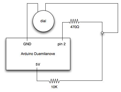
When the phone is being dialed, the switch opens and closes rapidly (for a 9, it will open and close again nine times, remember). When the switch is open, pin 2 is not connected to ground – instead it is connected to the 5V supply through a resistance of 10470 ohms. This is interpreted by the Arduino as a HIGH.
If your dial has a NORMALLY OPEN switch, then swapping the positions of the 10K resistor and the dial should do the trick.
Rotary phone dial
For more detail: Interface a rotary phone dial to an Arduino
- How do I remove the dial from the phone?
You may need to give it a tug if it pops straight out, or open the phone casing to figure out how to detach it. - What happens inside the dial when you spin it?
A switch makes and breaks the circuit rapidly, engaging once for each number digit dialed. - When does the actual dialing occur?
Dialing only happens when you let go of the number and allow it to spool back to the start. - How is the switch connected in this specific project?
The two sides of the switch are connected to the two leftmost terminals on the dial unit. - What signal does Pin 2 receive when the phone is not being dialed?
Pin 2 connects to ground through a 470 ohm resistor, registering as a LOW signal. - What signal does Pin 2 receive when the switch opens during dialing?
Pin 2 connects to the 5V supply through a resistance of 10470 ohms, which the Arduino interprets as HIGH. - What should I do if my dial has a normally open switch?
You should swap the positions of the 10K resistor and the dial unit. - Can I re-assemble the phone after modifying it?
Yes, but you must record which color wire goes to which connection before removing them.