
Summary of *IMPROVED* Smart LED Candle: Reactive to Sound and Aesthetically Pleasing
This article details an improved smart LED candle project that combines aesthetic design with reactive technology. The creator replaces a basic cardboard enclosure with a custom laser-cut wooden box to house the electronics and LEDs. The project utilizes an Arduino Uno to control LED lights based on ambient light levels detected by an LDR and sound input from a microphone sensor, creating a responsive and visually appealing device.
Parts used in the Improved Smart LED Candle:
- Arduino Uno
- 4x LED lights (Red and Blue)
- LDR / Photo resistor
- 4x 220 Ohm resistors
- 1x 10k Ohm resistor
- Arduino Compatible Microphone Sound Sensor Module
- Jumper wires (male to male and female to male)
- Custom container with two compartments
Remember the “smart” LED candle from a few months ago?
Well, the idea was nice, but the overall execution lacked some oomph. Technologically and aesthetically speaking there was a lot to improve.
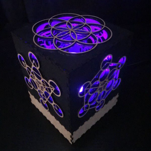
First off, as an artist, I wanted the container for the candle to look amazing. Or at least better than the old cardboard box I wrapped for the old project. At that time, I got encouraged at school to look into the art of lasercutting.
In this tutorial I am not going to cover the steps of how I made the box however, because that would be a full-on instructable in itself.
I would recommend to be creative and think outside of the box (har har) when making an aesthetically pleasing container for your own project.
It is a very rewarding experience when you are pushed outside of your comfort zone and to have learned a new skill in the end.
Step 1: Requirements
– Arduino Uno
– 4x LED lights (I used 2 red and 2 blue LEDs, but you can choose whatever colors you like)
– LDR / Photo resistor
– 4x 220 Ohm resistors
– 1x 10k Ohm resistor
– Arduino Compatible Microphone Sound Sensor Module (I used Velleman’s VMA309)
– Jumper wires, male to male and female to male
– Container of choice with 2 compartments; one to hide the electronics in and one to put your light in (I highly suggest making one yourself)
Step 2: Make a Fabulous Container for Your Project
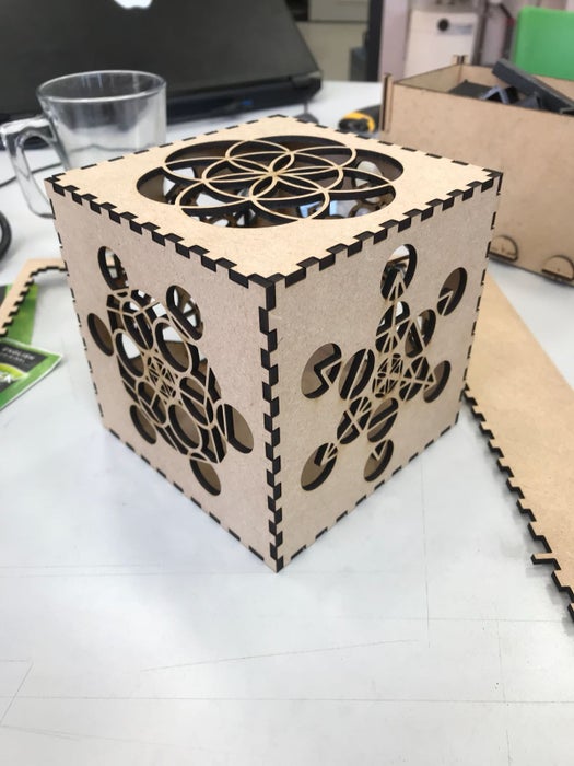
When it comes to choosing what type of container you want to make, the options are endless.
As long as one of the containers is open on at least one side (for the LEDs to be visible from the outside) and the other one closed (for the Arduino and all the wires to be invisible from the outside), you could go for any material, size or shape.
In my case I went for a wooden box with a laser cut design of geometrical shapes.
TIP: You can easily make a laser cutter ready plan for boxes like these in any size and even incorporate holes for wires and such with MakerCase. You can then load your plan into Adobe Illustrator and create your own design.
Step 3: Arduino: Breadboard & Schematics
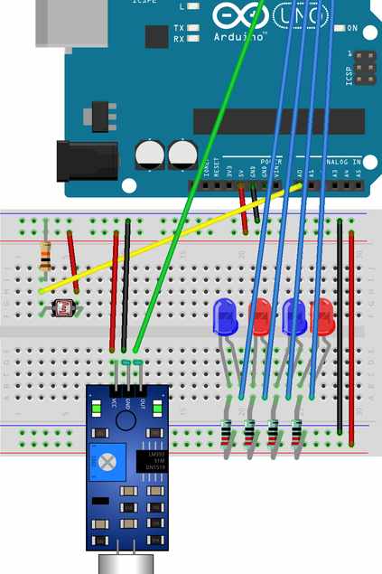
For visibility purposes the parts in the breadboard schematic are shown a little differently from the actual breadboard in the next steps, but don’t worry! The way everything is connected is the same.
– Red wires are + and go to the 5V pin
– Black wires are – and go to the GND pin
– Colored wires are to communicate with the Arduino; yellow for the LDR, green for the sound sensor and blue for the lights
Step 4: Assembling on Your Breadboard Part One: LDR
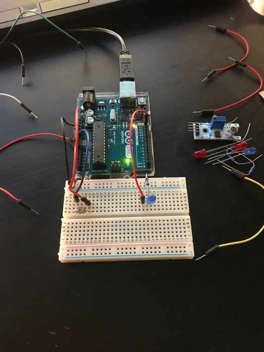
Start by sticking an LED light in your breadboard.
Connect the long leg (+) with a red jumper wire to digital pin 13 in the Arduino.
Connect the short leg (-) with a 220 Ohm resistor to the – side of your breadboard.
Insert the LDR in the breadboard and connect one leg to the 5V pin with a red wire.
Connect the other leg with a 10k Ohm resistor to the – side of your breadboard.
With a colored wire connect both the one resistor leg and 10k Ohm resistor to the A0 pin in the Arduino.
Lastly, connect the – of the breadboard with a black wire to the GND of the Arduino.
With the following code you should be able to turn the light on and off by exposing the LDR to brightness or darkness:
const int ledPin = 12;
const int ldrPin = A0;

void setup() {
  Serial.begin(9600);
  pinMode(ledPin, OUTPUT);
  pinMode(ldrPin, INPUT);

void loop() {
  int ldrStatus = analogRead(ldrPin);
  if (ldrStatus <300)
  {
    digitalWrite(ledPin, HIGH);
  }
  else
  {
    digitalWrite(ledPin, LOW);
  }
}
Step 5: Assembling on Your Breadboard Part Two: Sound Sensor
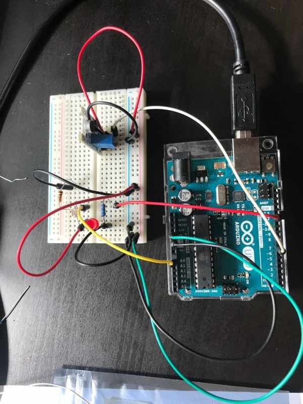
Stick the sound sensor in your breadboard.
Connect a red wire to the + of the sensor and put it in the breadboard’s +.
Connect a black wire to the GND of the sensor and put it in the breadboard’s -.
Connect a colored wire to the D0 of the sensor and put that in pin 7 of the Arduino.
Disconnect your LDR’s red wire from the 5V pin and put it in the breadboard’s +.
Now connect the breadboard’s – to the GND pin with a black wire and connect the breadboard’s + to the 5V pin with a red wire.
Put in the new code:
const int ledPin = 12;
const int ldrPin = A0;
const int micPin = 7;
int val = 0;

void setup() {
  Serial.begin(9600);
  pinMode(ledPin, OUTPUT);
  pinMode(ldrPin, INPUT);
  pinMode(micPin, INPUT);

void loop() {
  int ldrStatus = analogRead(ldrPin);
  val = digitalRead(micPin);
  if ((ldrStatus <300)&&(val == HIGH))
  {
    digitalWrite(ledPin, HIGH);
  }
  else
  {
    digitalWrite(ledPin, LOW);
  }
}
Source: IMPROVED Smart LED Candle: Reactive to Sound and Aesthetically Pleasing
-
What components are required for this project?
The project requires an Arduino Uno, four LED lights, an LDR, specific resistors, a sound sensor module, jumper wires, and a custom container. -
How can I make an aesthetically pleasing container for the project?
You can use a laser cutter to create a wooden box with geometric designs, ensuring one compartment is open for LEDs and the other is closed for electronics. -
Does the project react to both light and sound?
Yes, the code checks if the LDR status is below 300 and if the microphone sensor reads HIGH to turn the LED on. -
Which Arduino pins are used for the sensors and lights?
The LED connects to pin 12, the LDR connects to analog pin A0, and the sound sensor connects to digital pin 7. -
Can I choose different colors for the LEDs?
Yes, while the tutorial uses red and blue LEDs, you can choose whatever colors you like. -
What tool helps create laser cutter ready plans for boxes?
MakerCase allows you to easily make a laser cutter ready plan for boxes of any size and incorporate holes for wires. -
How do I connect the LDR to the power supply?
One leg of the LDR connects to the 5V pin with a red wire, and the other leg connects to the negative side via a 10k Ohm resistor. -
What is the purpose of the two compartments in the container?
One compartment hides the electronics and wires, while the other holds the light so it is visible from the outside.
