Summary of I2C With the ESP8266-01 !? || Exploring ESP8266:Part 1
This article demonstrates how to utilize the hidden I2C communication capability of the ESP8266-01 WiFi module, typically used for serial data, to drive an OLED display. The author explains the theoretical basis using the datasheet, details the physical wiring between the microcontroller and the screen, and provides a custom breadboard adapter solution for easier prototyping. Finally, the guide covers necessary software modifications using the Adafruit library to initialize GPIO pins as SDA and SCL, enabling the display of animations and custom text on this compact standalone board.
Parts used in the I2C With the ESP8266-01 project:
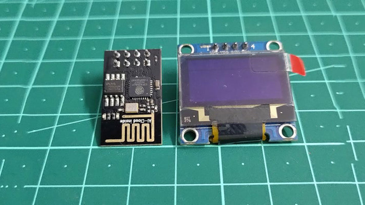
- ESP8266-01 WiFi Module
- OLED Display
- CH340G USB to serial converter
- Breadboard Friendly Breakout Board for ESP8266-01
- Voltage Regulator
- MicroUSB port
- GPIO and power pins female header
- Toggle switch
- LEDs
Hello all ! With this instructable I will be writing and documenting a series of projects mentioning and exploring the various hidden ( rather unexplored ) features of the tiny ESP8266-01 WiFi Module.
Did you know that the ESP8266-01 supports I2C communication? Yes it is true, this little module lying unattended in one corner of your electronics bench has the capability to support this amazing communication protocol. This module is mainly used to connect and provide WiFi connectivity to a project using the serial communication involving Tx and Rx pins of the module. But in reality this cheap module is in itself a very capable microcontroller that can be used as standalone projects as well.
In this instructable we will be exploring the I2C communication protocol and interfacing an OLED display to show some animations and custom data as well.
So without any further delay let’s jump into some theory and finally a practical application showing the hidden talents of this little buddy!
Step 1: First: Checking the Datasheet
The main microcontroller of the ESP8266-01 module is Espressif’s ESP8266EX which is pretty powerful as compared to the more popular microcontrollers on the arduino.
This little thing has the following specifications:
- CPU : Tensilica L106 32-bit processor
- 1 MB of programmable memory!
- A good range of communication protocols like: I2S,I2C, UART and SPI
- It also has a PWM feature and interestingly also an ADC!
Okay so enough of good talks.Does this acually support I2C? Yes,and a quick look through the data sheet confirms this feature as well.
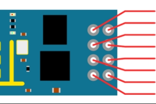
In this step I have attached the snapshots of the sections of datasheet that clearly mentions the communication capability and the pins required for I2C connections.
I2C is a very powerful communication protocol and used just 2 pins to communicate:
- The SDA (this is the data pin)
- The SCL (or SCK in some cases, this is the clock pin)
Systems connected via I2C have a master slave kind of communication topology. Here we can have multiple masters and multiple slave devices as well. But how does a master device specifically communicate with a particular slave? Well here each device has a unique address of itself that can be used to access(or communicate) with that particular device. The device can be a output device, like the very popular OLED screens or it can also be an input device like the MPU6050 or a BMP180 sensor.
So coming back to the ESP8266, I have attached snapshots of the part of datasheet that mention I2C details. Here the main thing is that the SDA or the data pin is actually the GPIO2 pin which is available in the pinout of the WiFi module. What about the the SCL pin? Well, we only have the GPIO 0 pin left as an available pin so we can assign it as a SCL pin-more on this during the coding process.
I have also attached the datasheet for your reference
Step 2: Connecting Up the Modules
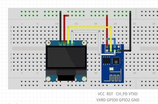
We now have a basic understanding of how I2C works and it’s possible to implement the same in our ESP8266 module. In this step you can see a basic connection overview for the ESP8266 and the OLED display. As you can see that both module have a common power supply which ideally should be 3.3volts to 2.7volts at max as the ESP is a 3.3V compatible device and any higher voltage may potentially damage the board. But I have tested this board and does work at 5 volts logic though it gets more heated up, so let’s not take any risk and stick to 3.3volts supply. here the GPIO2 is tied to SDA and the GOIP0 to SCK. The CH_PD is tied to Vcc to enable the module’s functionality.
Step 3: Breadboard Setup

Now to test this setup, I have previously made a few mods and adapters so that I can easily program and fix the ESP8266 on to the breadboard. You know that ESP8266 is not a breadboard friendly module so I made a tiny little adapter that lets me plug the most important pins on to a bread board and access it conveniently.
I do have a instructable for that:
Breadboard Friendly Breakout Board for ESP8266-01: https://www.instructables.com/Breadboard-Friendly-…
You can go through this instructable to make your own little adapter in very less time.
Next up is programming: For this I have used the CH340G USB to serial converter which can communicate with the ESP via serial interface and upload codes accordingly.
I have also set this up on a bradboard,you can also buy those readymade CH340 programmer boards on which you can directly plug the ESP for programming. I personally wanted all of them to be on a breadboard so I made my choices.
In the first Image you can see the setup of the ESP along with the programmer setup.
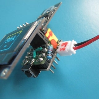
In the next image, you can see the that I have soldered 2 wires underneath my ESP adapter to the GPIO pins which to the SDA and SCL of the OLED display. I have already loaded an animation code and it successfully displays those flawlessly.
What about the code you ask? Well, it’s the next step
Step 4: The Coding..
To upload some test code is the next obvious thing to do and I thought of uploading the sample animations sketch that the Adafruit OLED library provides.
The link to the Library is: https://github.com/adafruit/Adafruit_SSD1306
The code definitely needs to be modified in order for the ESP to work and communicate with the OLED-Here in the code we also specify GPIO as the SCK pin.
Here is a brief summary of the code, which for your reference is also attached in this step.
- Importing the Libraries that are used for initialising and setting up the OLED display
- Importing the Wire Library for the I2C communication.
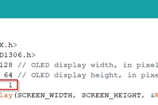
- Setting up the width and height of the OLED
- Initialising GPIO 0 as the SDA pin
- Specifying the OLED address and setting up the text size and colour of the display
- The remaining part of the code can be found in the Adafruit library example. I have just added hose codes from there.
With everything in place, now we have to select the proper COM port and select generic ESP8266 as our target board.You can check the code snippets in this step.
Step 5: Making Things a Little Easier..
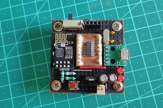
To make working with ESP8266-01 a little easier, I decided to make a sort of development board for the same. This little board includes the following:
- USB to serial programmer
- A microUSB port for programming
- A voltage regulator
- GPIO and power pins female header
- A switch to toggle between programming mode and running mode
- LED’s to indicate data communication
With this is is way more easier to upload and test programs and I have made the pinout in such a way that I can plug the OLED directly into the female headers!
I am sure this will be very helpful for you and if you wish to make this well then you guessed it right, I have a instructable for this as well 🙂
ESP-O-One : Making Your Own ESP Development Board :https://www.instructables.com/ESP-O-One-Making-You…
Step 6: Final Words
Phew! I feel that knowing this cool feature opens up a lot of possibilities with this powerful and minimalistic board because we know that a lot of sensors and devices use I2C communication.
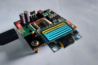
You can see that I have attached the OLED with my development board running the animations sketch and I hope that this information would help you in many ways to experiment with this board.
Feel free to share your feedbacks and suggestions in the comment section below and do watch the video at the beginning of the tutorial so as to get detailed information about this project and while you are there, don’t forget to give that video a like and even consider subscribing! that would be awesome.
I will be documenting the later stages of this project and other capabilities of the ESP boards as mentioned earlier. Thanks again for going through my instructable and have a good day!
2 People Made This Project!
Source: I2C With the ESP8266-01 !? || Exploring ESP8266:Part 1
- Does the ESP8266-01 support I2C communication?
Yes, the ESP8266-01 supports I2C communication despite being mainly used for serial connections. - Which pins are required for I2C connections?
I2C uses two pins: SDA for data and SCL (or SCK) for the clock signal. - What voltage supply should be used for the ESP8266 and OLED?
A common power supply of 3.3 volts to 2.7 volts is recommended to avoid damaging the board. - How do you connect the ESP8266-01 to an OLED display for I2C?
Connect GPIO2 to the SDA pin and GPIO0 to the SCL or SCK pin on the OLED display. - Which library is used for initializing the OLED display in the code?
The Adafruit SSD1306 library is used along with the Wire Library for I2C communication. - Can the ESP8266-01 work at 5 volts logic?
It can work at 5 volts logic but it gets more heated up, so 3.3 volts is safer. - What is the purpose of the CH340G USB to serial converter?
It communicates with the ESP via serial interface to upload codes accordingly. - How does a master device communicate with a specific slave device in I2C?
Each device has a unique address that allows the master to access or communicate with that particular device.